AUDIO AND VISUAL SYSTEM (w/o Microphone), Diagnostic DTC:01-D5, 01-D8, 01-D9, 01-DA, 01-DB, 01-DC, 01-DE

| DTC Code | DTC Name |
|---|---|
| 01-D5 | Absence of Registration Unit (AUDIO H/U) |
| 01-D8 | No Response for Connection Check (AUDIO H/U) |
| 01-D9 | Last Mode Error (AUDIO H/U) |
| 01-DA | No Response Against ON / OFF Command (AUDIO H/U) |
| 01-DB | Mode Status Error (AUDIO H/U) |
| 01-DC | Failure in Transmission (AUDIO H/U) |
| 01-DE | Slave Reset (AUDIO H/U) |
DESCRIPTION
| DTC No. | DTC Detection Condition | Trouble Area |
|---|---|---|
| 01-D5 *1, *5 |
The device that the sub code shows is (was) disconnected from the system when turning the ignition switch to the ACC or ON position. The communication with the device that the code shows cannot be established when the engine starts. | Inspection of the device indicated by the sub code. (Refer to the inspection list for the device indicated by the sub code.) |
| 01-D8 *2, *5 |
The device indicated by the sub code is (was) disconnected from the system after engine start. | |
| 01-D9 *1, *5 |
The device (for audio visual system) that had functioned before the engine stopped is(was) disconnected from the system when the ignition switch is(was) in the ACC or ON position | |
| 01-DA *5 |
No response is identified when changing mode (audio and visual mode change). Detected when sound and image do not change despite switch operation. | |
| 01-DB *1, *5 |
This code detects a dual alarm. | |
| 01-DC *3, *5 |
This code indicates a transmission failure of the device indicated by the sub code. NOTE: This DTC may have no direct relationship with the malfunction. |
|
| 01-DE *4, *5 |
This code is stored when a slave device has been disconnected after engine start. |
Tech Tips
-
*1: Even if no failure is detected, a trouble code may be recorded depending on the battery condition or engine start voltage.
-
*2: If the power connector is disconnected after the engine starts, this code is recorded after 180 seconds.
*3: This code may be stored if the ignition key is turned again after the engine starts.
-
*4: This code may be stored if the ignition key is held in the START position for one minute or more before returning to the ON position.
-
*5: If the device is reported as not existing during verification, check the power source circuit and AVC-LAN circuit for the device.
INSPECTION PROCEDURE
Tech Tips
Methods used to verify the cause of the problem are listed in the order of probability of the trouble areas.
The sub code is always displayed together with the diagnostic code if it is registered.
PROCEDURE
-
INSPECT POWER SOURCE CIRCUIT (RADIO RECEIVER)
-
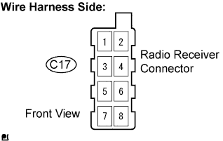
Disconnect the C17 radio receiver connector.
-
Check the resistance.
Standard Resistance Tester Connection Condition Specified Condition GND (C17-8) - Body ground Constant Below 1 Ω -
Turn the ignition switch to the ACC position.
-
Measure the voltage.
Standard Voltage Tester Connection Condition Specified Condition B (C17-7) - GND (C17-8) Constant 10 to 14 V ACC (C17-4) - GND (C17-8) Ignition switch ACC or ON 10 to 14 V -
Reconnect the radio receiver connector.
NG 
REPAIR OR REPLACE HARNESS OR CONNECTOR
OK 
REPLACE RADIO RECEIVER
-