AUDIO AND VISUAL SYSTEM (w/o Microphone) DTC CHECK / CLEAR

-
START DIAGNOSTIC MODE (ALL ELEMENTS COME ON DURING THE SWITCH CHECK MODE)

-
Turn off the audio system and turn the ignition switch to the ACC position. While pressing preset switches "1" and "6" at the same time, press "CD/AUX" 3 times.
-
Reference:
-
When the system enters the diagnosis mode, a beep sound is emitted 3 times and all the elements come on during the switch check mode.
-
It takes about 40 seconds to complete the check.
-
Turn all the elements in the LCD on.
-
When pressing the switches 1 and 6, confirm beep sound is emitted.
-
Press the "TUNE TRACK" switch to enter the "System Check Screen".
-
-
-
SYSTEM CHECK SCREEN
-
Reference:
-
In the system check mode, the system check and the diagnostic memory check are performed, and the check results are displayed in ascending order of the component codes (physical address).
Terms Meaning Component code
(Physical address)
Three-digit code (In hexadecimal) given to each device comprising AVC-LAN. Corresponding to its function, individual symbol is provided. Logical address Two-digit code (In hexadecimal) given to each function and device unit comprising AVC-LAN. -
-
-
READ THE SYSTEM CHECK RESULT

-
Press the "TUNE TRACK" switch to see the check results for each component.
Tech Tips
Press the upper portion of the "TUNE TRACK" switch first.
-
The component code (physical address) is displayed first, and then the check result follows.
Tech Tips
-
If all check results are "good", the system determines that no DTC exists.
-
P190 is not a DTC that indicates a specific malfunction.
-
-
-
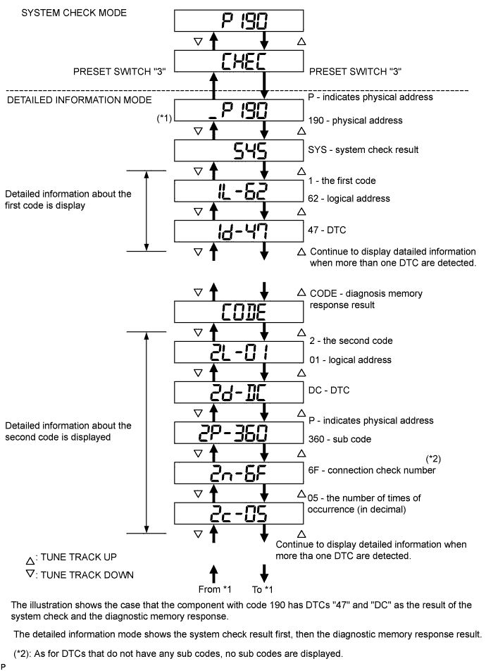
DETAILED INFORMATION MODE (WHEN DISPLAYING THE DTC FOR A TROUBLE COMPONENT)

-
When "CHEC" or "ECHN" is displayed, press preset switch "2" to go to the detailed information mode.
-
Press the "TUNE TRACK" switch to display the "System check result (SYS)" and "Diagnostic memory response (CODE)".
-
Display items in detailed information mode.
Division Code for DTC Display Description Display Order of Detailed Information SYS System check result is displayed Logical Address
↓
DTC
CODE Diagnostic memory check result is displayed Logical Address
↓
DTC
↓
Sub Code
↓
Connection Confirmation Number
↓
Number of occurrences
Tech Tips
The information is displayed in the order shown in the table above when the TURN UP switch is pressed. To reverse the order, press the TURN DOWN switch.
-
Check the trouble area by referring to the DTC chart.
-
To return to the service check mode, press preset switch "3"
-
-
Clearance of individual DTC Memories (when clearing each memory of the DTCs detected in the past individually)
-
Press preset switch "5" for 2 seconds or more while "ECHN" is displayed in the system check mode or during the detailed information mode.
Tech Tips
-
A beep sound is emitted once when the DTC memory clearance is completed.
-
When the DTC memory is cleared, only the component code (physical address) is displayed for the target component.
-
To check DTCs, press preset switch "1" and perform the system check again.
-
-
-
Clearance of all the DTC memories (when clearing all the memories of the DTCs detected in the past simultaneously)
-
Start the diagnostic mode after repairing the trouble area.
-
Press preset switch "5" for 2 seconds or more. ("CLR" is displayed at this time.)
Tech Tips
-
A beep sound is emitted once when the DTC memory clearance is completed.
-
When the DTC memory is cleared, only the component code (physical address) is displayed for the target component.
-
-
Press preset switch "1" to perform the service check again, and check that no DTCs are displayed for any of the component codes (physical addresses).
-