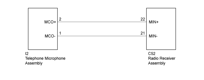
AUDIO AND VISUAL SYSTEM (w/ Microphone) Microphone Circuit between Microphone and Radio Receiver
DESCRIPTION
This circuit sends a microphone signals from the telephone microphone assembly to the radio receiver assembly.
WIRING DIAGRAM
INSPECTION PROCEDURE
PROCEDURE
-
CHECK HARNESS AND CONNECTOR (RADIO RECEIVER ASSEMBLY - TELEPHONE MICROPHONE ASSEMBLY)
-
Disconnect the C52 radio receiver assembly connector.
-
Disconnect the I2 telephone microphone assembly connector.
-
Measure the resistance according to the value(s) in the table below.
Standard Resistance Tester Connection Condition Specified Condition C52-22 (MIN+) - I2-2 (MCO+) Always Below 1 Ω C52-21 (MIN-) - I2-1 (MCO-) Always Below 1 Ω C52-22 (MIN+) - Body ground Always 10 kΩ or higher C52-21 (MIN-) - Body ground Always 10 kΩ or higher
NG 
REPAIR OR REPLACE HARNESS OR CONNECTOR
OK 
PROCEED TO NEXT SUSPECTED AREA SHOWN IN PROBLEM SYMPTOMS TABLE Click here
-