METER / GAUGE SYSTEM Warning Buzzer does not Sound
DESCRIPTION
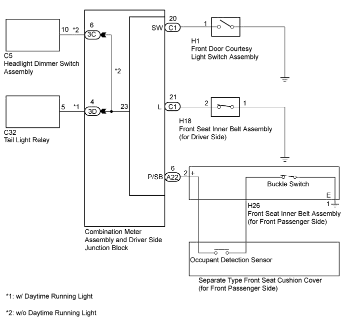
The combination meter assembly controls the buzzers in accordance with signals from the front seat inner belt assembly (for driver side), the front seat inner belt assembly (for front passenger side), the front door courtesy light switch assembly and the tail light relay.
WIRING DIAGRAM
INSPECTION PROCEDURE
PROCEDURE
-
CHECK BUZZER
-
Operate the buzzers and check that those for the seat belt warning and light reminder warning sound normally.
Result Result Proceed to No warning buzzers sound A Seat belt warning does not sound (for Driver Side) B Seat belt warning does not sound (for Front Passenger Side) C Light reminder warning does not sound (w/ Daytime Running Light) D Light reminder warning does not sound (w/o Daytime Running Light) E Tech Tips
-
Light reminder buzzer: Ignition switch is off, tail lights are on and door is open.
-
Seat belt buzzer: Ignition switch is on and seat belt is unfastened.
-
B 
INSPECT FRONT SEAT INNER BELT ASSEMBLY (FOR DRIVER SIDE) Click here
C
INSPECT OCCUPANT DETECTION SENSOR Click here
D
INSPECT FRONT DOOR COURTESY LIGHT SWITCH ASSEMBLY Click here
E
INSPECT FRONT DOOR COURTESY LIGHT SWITCH ASSEMBLY Click here
A 
REPLACE COMBINATION METER ASSEMBLY
-
-
INSPECT FRONT SEAT INNER BELT ASSEMBLY (FOR DRIVER SIDE)
-
Remove the front seat inner belt assembly (for driver side) Click here.
-
Inspect the front seat inner belt assembly (for driver side) Click here.
NG 
REPLACE FRONT SEAT INNER BELT ASSEMBLY (FOR DRIVER SIDE) Click here
OK 
-
-
CHECK HARNESS AND CONNECTOR (FRONT SEAT INNER BELT ASSEMBLY (FOR DRIVER SIDE) - COMBINATION METER ASSEMBLY)
-
Disconnect the C1 combination meter assembly connector.
-
Disconnect the H18 front seat inner belt assembly (for Driver Side) connector.
-
Measure the resistance according to the value(s) in the table below.
Standard Resistance Tester Connection Condition Specified Condition C1-21 (L) - H18-2 Always Below 1 Ω C1-21 (L) or H18-2 - Body ground Always 10 kΩ or higher
NG
REPAIR OR REPLACE HARNESS OR CONNECTOR
OK
REPLACE COMBINATION METER ASSEMBLY Click here
-
-
INSPECT OCCUPANT DETECTION SENSOR
-
Remove the occupant detection sensor Click here.
-
Inspect the occupant detection sensor Click here.
NG
REPLACE OCCUPANT DETECTION SENSOR Click here
OK
-
-
INSPECT FRONT SEAT INNER BELT ASSEMBLY (FOR FRONT PASSENGER SIDE)
-
Remove the front seat inner belt assembly (for front passenger side) Click here.
-
Inspect the front seat inner belt assembly (for front passenger side) Click here.
NG
REPLACE FRONT SEAT INNER BELT ASSEMBLY (FOR FRONT PASSENGER SIDE) Click here
OK
-
-
CHECK HARNESS AND CONNECTOR (FRONT SEAT INNER BELT ASSEMBLY (FOR FRONT PASSENGER SIDE) - COMBINATION METER ASSEMBLY)
-
Disconnect the H26 front seat inner belt assembly (for front passenger side) connector.
-
Disconnect the A22 combination meter assembly connector.
-
Measure the resistance according to the value(s) in the table below.
Standard Resistance Tester Connection Condition Specified Condition A22-6 (P/SB) - H26-2 (+) Always Below 1 Ω H26-1 (E) - Body ground Always Below 1 Ω A22-6 (P/SB) - Body ground Always 10 kΩ or higher
NG
REPAIR OR REPLACE HARNESS OR CONNECTOR
OK
REPLACE COMBINATION METER ASSEMBLY Click here
-
-
INSPECT FRONT DOOR COURTESY LIGHT SWITCH ASSEMBLY
-
Remove the front door courtesy light switch assembly Click here.
-
Inspect the front door courtesy light switch assembly Click here.
NG
REPLACE FRONT DOOR COURTESY LIGHT SWITCH ASSEMBLY Click here
OK
-
-
CHECK HARNESS AND CONNECTOR (FRONT DOOR COURTESY LIGHT SWITCH ASSEMBLY - COMBINATION METER ASSEMBLY)
-
Disconnect the H1 front door courtesy light switch assembly connector.
-
Disconnect the C1 combination meter assembly connector.
-
Measure the resistance according to the value(s) in the table below.
Standard Resistance Tester Connection Condition Specified Condition C1-20 - H1-1 Always Below 1 Ω C1-20 or H1-1 - Body ground Always 10 kΩ or higher
NG
REPAIR OR REPLACE HARNESS OR CONNECTOR
OK
-
-
INSPECT TAIL LIGHT RELAY
-
Remove the tail light relay Click here.
-
Inspect the tail light relay Click here.
NG
REPLACE TAIL LIGHT RELAY Click here
OK
-
-
CHECK HARNESS AND CONNECTOR (TAIL LIGHT RELAY - COMBINATION METER ASSEMBLY)
-
Disconnect the C32 tail light relay connector.
-
Disconnect the 3D driver side junction block connector.
-
Measure the resistance according to the value(s) in the table below.
Standard Resistance Tester Connection Condition Specified Condition 3D-4 - C32-5 Always Below 1 Ω 3D-4 or C32-5 - Body ground Always 10 kΩ or higher
NG
REPAIR OR REPLACE HARNESS OR CONNECTOR
OK
REPLACE COMBINATION METER ASSEMBLY Click here
-
-
INSPECT FRONT DOOR COURTESY LIGHT SWITCH ASSEMBLY
-
Remove the front door courtesy light switch assembly Click here.
-
Inspect the front door courtesy light switch assembly Click here.
NG
REPLACE FRONT DOOR COURTESY LIGHT SWITCH ASSEMBLY Click here
OK
-
-
CHECK HARNESS AND CONNECTOR (FRONT DOOR COURTESY LIGHT SWITCH ASSEMBLY - COMBINATION METER ASSEMBLY)
-
Disconnect the H1 front door courtesy light switch assembly connector.
-
Disconnect the C1 combination meter assembly connector.
-
Measure the resistance according to the value(s) in the table below.
Standard Resistance Tester Connection Condition Specified Condition C1-20 - H1-1 Always Below 1 Ω C1-21 or H18-2 - Body ground Always 10 kΩ or higher
NG
REPAIR OR REPLACE HARNESS OR CONNECTOR
OK
-
-
INSPECT HEADLIGHT DIMMER SWITCH ASSEMBLY
-
Remove the headlight dimmer switch assembly Click here.
-
Inspect the headlight dimmer switch assembly Click here.
NG
REPLACE HEADLIGHT DIMMER SWITCH ASSEMBLY Click here
OK
-
-
CHECK HARNESS AND CONNECTOR (HEADLIGHT DIMMER SWITCH ASSEMBLY - COMBINATION METER ASSEMBLY)
-
Disconnect the C5 headlight dimmer switch assembly connector.
-
Disconnect the 3C driver side junction block connector.
-
Measure the resistance according to the value(s) in the table below.
Standard Resistance Tester Connection Condition Specified Condition 3C-6 - C5-10 Always Below 1 Ω 3C-6 or C5-10 - Body ground Always 10 kΩ or higher
NG
REPAIR OR REPLACE HARNESS OR CONNECTOR
OK
REPLACE COMBINATION METER ASSEMBLY Click here
-