AUDIO AND VISUAL SYSTEM (w/o Microphone) Radio Receiver Power Source Circuit
DESCRIPTION
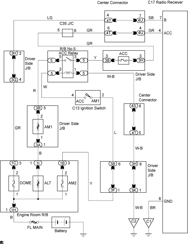
This circuit provides power to the radio receiver.
WIRING DIAGRAM
INSPECTION PROCEDURE
PROCEDURE
-
INSPECT RADIO RECEIVER
-
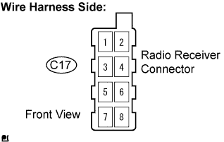
Disconnect the C17 radio receiver connector.
-
Check the resistance.
Standard Resistance Tester Connection Condition Specified Condition GND (C17-8) - Body ground Constant Below 1 Ω -
Turn the ignition switch to the ACC position.
-
Measure the voltage.
Standard Voltage Tester Connection Condition Specified Condition B (C17-7) - GND (C17-8) Constant 10 to 14 V ACC (C17-4) - GND (C17-8) Ignition switch ACC or ON 10 to 14 V -
Reconnect the radio receiver connectors.
NG 
REPAIR OR REPLACE HARNESS OR CONNECTOR
OK 
PROCEED TO NEXT CIRCUIT INSPECTION SHOWN IN PROBLEM SYMPTOMS TABLE
-