METER / GAUGE SYSTEM TERMINALS OF ECU

-
COMBINATION METER ASSEMBLY (COMBINATION METER SIDE)
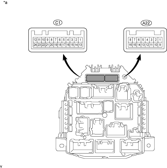
Text in Illustration *a Combination Meter Side - -
-
Measure the voltage, resistance and check for pulse according to the value(s) in the table below.
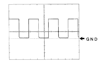
Terminals No. (Symbol) Wiring Color Terminal Description Condition Specified Condition A22-4 (BRQ) - Body ground*1 R - Body ground Multi-mode manual transaxle signal Multi-mode manual transaxle warning light on 4.5 to 5.5 V Multi-mode manual transaxle warning light off Below 1 V A22-5 (TX+) - Body ground*1 Y - Body ground Multi-mode manual transaxle position signal Multi-mode manual transaxle position indicator on Pulse generation Multi-mode manual transaxle position indicator off Below 1 V A22-6 (P/SB) - Body ground GR - Body ground Front passenger seat belt signal Front passenger seat occupied, seat belt fastened Below 1 V Front passenger seat occupied, seat belt unfastened 11 to 14 V A22-7 (H) - Body ground W - Body ground High engine coolant temperature Ignition switch ON, engine coolant temperature 117°C (243°F) or more Below 1 V A22-8 (S) - Body ground O - Body ground Oil pressure signal Oil pressure warning light on Below 1 V Oil pressure warning light off 11 to 14 V A22-9 (FR FOG) - Body ground*2 R - Body ground Front fog light signal Front fog light on 11 to 14 V Front fog light off Below 1 V A22-10 (TRC) - Body ground*3 G - Body ground TRC signal Slip indicator light off 11 to 14 V Slip indicator light on Below 1 V A22-11 (VSW) - Body ground*3 L - Body ground VSC signal VSC warning light off 11 to 14 V VSC warning light on Below 1 V A22-13 (SW) - Body ground LG - Body ground BRAKE signal BRAKE warning light on Below 1 V BRAKE warning light off 11 to 14 V A22-14 (EFI) - Body ground BR - Body ground MIL signal MIL on Below 1 V MIL off 11 to 14 V A22-15 (EBD) - Body ground W - Body ground EBD signal BRAKE warning light off Below 1 V BRAKE warning light on 11 to 14 V A22-16 (LP) - Body ground P - Body ground ABS signal ABS warning light off Below 1 V ABS warning light on 11 to 14 V C1-13 (HAZ) - Body ground Y - Body ground Hazard signal Hazard on Below 1 V Hazard off 11 to 14 V C1-14 (L) - Body ground W - Body ground Fuel level signal Ignition switch ON, fuel level FULL → EMPTY 410 Ω C1-15 (DRLE) - Body ground*4 GR - Body ground Daytime running light Signal Daytime running light off 11 to 14 V Daytime running light on Below 1 V C1-16 (ES) - Body ground O - Body ground Ground Always Below 1 V C1-17 (ET) - Body ground SB - Body ground Ground Always Below 1 V C1-19 (SW) - Body ground GR - Body ground Airbag signal AIRBAG warning light on Pulse generation AIRBAG warning light off Pulse generation C1-20 (SW) - Body ground LG - Body ground Driver side door condition signal Driver side door open Below 1 V Driver side door closed 11 to 14 V C1-21 (L)- Body ground Y - Body ground Driver seat belt signal FASTEN BELT indicator light on Below 1 V FASTEN BELT indicator light off 11 to 14 V C1-22 (SI) - Body ground W - Body ground Vehicle speed signal (Input) Ignition switch ON and wheel turning slowly Pulse generation
(See waveform 1)
C1-23 (EMPS) - Body ground G - Body ground EPS signal EPS warning light off Below 1 V EPS warning light on 11 to 14 V C1-24 (CHG-) - Body ground V - Body ground Charge signal Idling 11 to 14 V Ignition switch off Below 1 V
-
*1: for Multi-mode Manual Transaxle
-
*2: w/ Fog Light
-
*3: w/ VSC
-
*4: w/ Daytime Running Light
-
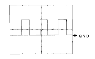
Waveform 1
Item Contents Tool setting 5 V/DIV, 20 ms/DIV Vehicle condition Driving at approximately 20 km/h (12 mph) Tech Tips
As the vehicle speed increases, the cycle of the signal waveform narrows.
-
-
-
COMBINATION METER ASSEMBLY (DRIVER SIDE JUNCTION BLOCK SIDE)
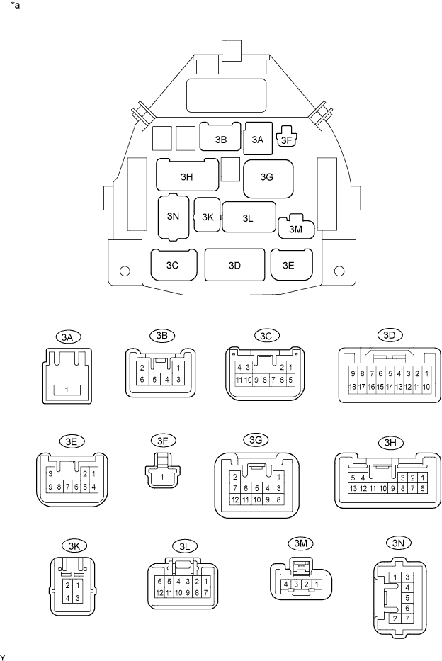
Text in Illustration *a Driver Side Junction Block Side - -
-
Measure the voltage and resistance according to the value(s) in the table below.
Terminals No. (Symbol) Wiring Color Terminal Description Condition Specified Condition 3C-4 - Body ground B - Body ground Turn signal LH Turn signal LH on Below 1 V Turn signal LH off 11 to 14 V 3C-5 - Body ground P - Body ground Hi-Beam signal Hi-Beam off Below 1 V Hi-Beam on 11 to 14 V 3C-9 - Body ground Y - Body ground Turn signal RH Turn signal RH on Below 1 V Turn signal RH off 11 to 14 V 3C-10 - Body ground R - Body ground Rear fog signal Rear fog on 11 to 14 V Rear fog off Below 1 V 3C-11 - Body ground L - Body ground Lo-Beam signal Lo-Beam off Below 1 V Lo-Beam on 11 to 14 V 3D-2 - Body ground O - Body ground Ground Always Below 1 V 3D-4 - Body ground SB - Body ground Illumination signal Taillight off Below 1 V Taillight on 11 to 14 V 3D-10 - Body ground BR - Body ground Ground Always Below 1 V 3D-15 - Body ground LG - Body ground Rear fog signal Rear fog on 11 to 14 V Rear fog off Below 1 V 3G-2 - Body ground Y - Body ground Power source for flasher relay Always 11 to 14 V 3G-4 - Body ground GR - Body ground Battery Always 11 to 14 V 3G-10 - Body ground P - Body ground Hi-Beam signal Hi-Beam off Below 1 V Hi-Beam on 11 to 14 V 3H-9 - Body ground Y - Body ground Ignition switch signal Ignition switch off Below 1 V 45 kΩ Ignition switch ON 11 to 14 V 3K-1 - Body ground W-B - Body ground Ground Always Below 1 Ω 3L-6 - Body ground LG - Body ground Lo-Beam signal Lo-Beam off Below 1 V Lo-Beam on 11 to 14 V 3L-8 - Body ground W - Body ground Ground Always Below 1 V 3L-9 - Body ground Y - Body ground Ground Always Below 1 V 3L-10 - Body ground O - Body ground Ground Always Below 1 V 3L-11 - Body ground V - Body ground Ground Always Below 1 V 3N-5 - Body ground G - Body ground Illumination signal Taillight off Below 1 V Taillight on 11 to 14 V
-
-
COMBINATION METER INNER CIRCUIT
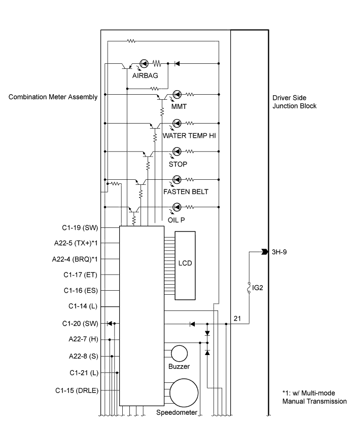
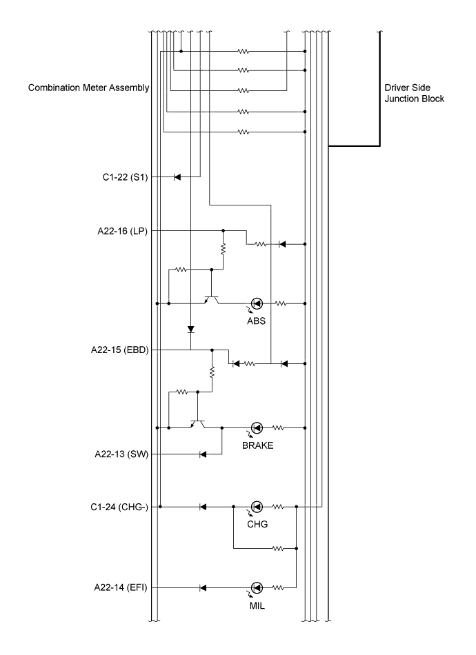
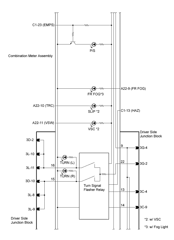
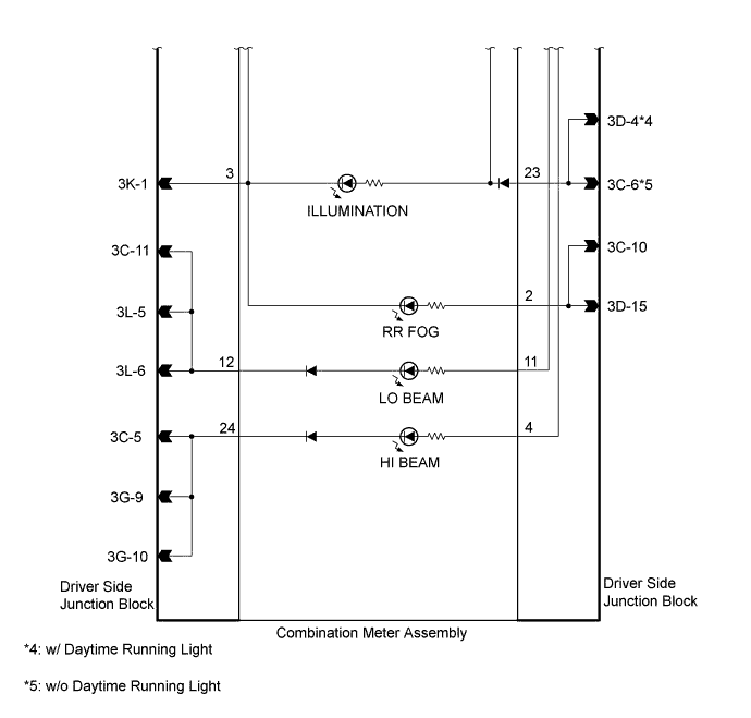
Connectors: Terminal No. Wire Harness Side A22 4 Multi-mode Manual Transmission Control ECU*1 5 Multi-mode Manual Transmission Control ECU*1 6 Front Seat Inner Belt Assembly (for Front Passenger Side) 7 ECM 8 Oil Pressure Switch 9 FR FOG Relay*2 10 Skid Control ECU*3 11 Skid Control ECU *3 13 Brake Fluid Level Warning Switch 14 ECM 15 Skid Control ECU 16 Skid Control ECU C1 13 Hazard Warning Signal Switch Assembly 14 Fuel Sender Gauge 15 DRL Relay*4 16 Fuel Sender Gauge 17 Ground 19 Airbag Sensor Assembly 20 Door Courtesy Light Switch 21 Front Seat Belt Inner Belt Assembly (for Driver Side) 22 Skid Control ECU 23 Power Steering ECU 24 Generator (Alternator) 3C 4 Combination Switch 5 Combination Switch 6 Combination Switch 9 Combination Switch 10 Combination Switch 11 Combination Switch*5 3D 2 Rear Combination Light (LH) 4 TAIL Relay*4 10 Rear Combination Light (RH) 15 Rear Combination Light (RH LH) 3G 2 Battery 4 Battery 10 Headlight (HI RH) 3H 9 Ignition Switch 3K 1 Ground 3L 6 Headlight (LO RH) 8 Turn Signal Light (Front Side RH) 9 Turn Signal Light (Front RH) 10 Turn Signal Light (Front Side LH) 11 Turn Signal Light (Front LH)
-
*1: for Multi-mode Manual Transaxle
-
*2: w/ Fog Light
-
*3: w/ VSC
-
*4: w/ Daytime Running Light
-
*5: w/o Daytime Running Light
-
-
TACHOMETER
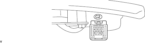
Symbols (Terminals No.) Wiring Color Terminal Description Condition Specified Condition B (C2-5) - Body ground L - Body ground Battery Always 11 to 14 V IG+ (C2-1) - Body ground R - Body ground Battery Ignition switch ON 11 to 14 V IG+ (C2-1) - Body ground R - Body ground Battery Ignition switch off Below 1 V S (C2-2) - Body ground B - Body ground Tacho signal (Input) Engine idling speed Pulse generation (See waveform 1) E (C2-4) - Body ground BR - Body ground Ground Always Below 1 Ω ILL+ (C2-6) - Body ground G - Body ground Illumination signal Taillight off Below 1 Ω ILL+ (C2-6) - Body ground G - Body ground Illumination signal Taillight on 11 to 14 V
-
Using an oscilloscope, check waveform 1.
Waveform 1 (Reference) Item Contents Tool setting 5 V/DIV, 10 ms/DIV Vehicle condition Engine idling speed
-