FRONT DOOR LOCK INSTALLATION

-
INSTALL FRONT DOOR LOCK ACTUATOR ASSEMBLY
-
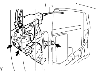
Install the front door lock actuator assembly with the 2 screws.
-
-
INSTALL FRONT DOOR LOCK ASSEMBLY
-
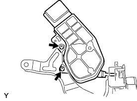
Apply MP grease to the sliding and rotating components of the front door lock assembly.
-
Apply adhesive to the threads of the 3 screws.
Adhesive Toyota Genuine Adhesive 1324, Three Bond 1324 or equivalent -
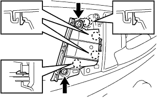
Using T30 "TORX" socket wrench, install the front door lock assembly with the 3 screws.
- Torque:
- 5.0 N*m { 51 kgf*cm, 44 in.*lbf }
-
Install the bolt.
- Torque:
- 5.0 N*m { 51 kgf*cm, 44 in.*lbf }
-
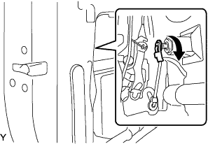
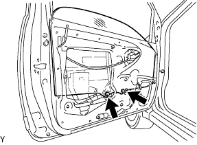
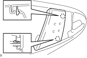
Connect the front door outside locking link, as shown in the illustration.
-
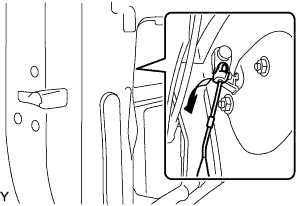
Connect the front door lock open rod, as shown in the illustration.
-
-
INSTALL FRONT DOOR INSIDE HANDLE SUB-ASSEMBLY
-
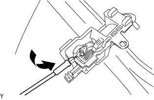
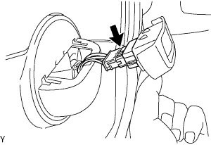
Connect the cable to the front door inside handle sub-assembly by turning it in the direction shown in the illustration.
-
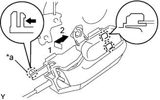
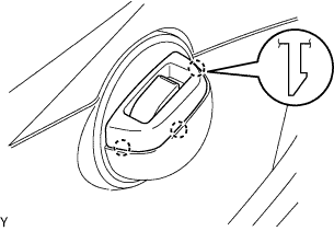
Move the front door inside handle sub-assembly in the direction indicated by the arrow in the illustration. This will engage the 2 claws and allow the installation of the front door inside handle sub-assembly.
-
Engage claw A.
Text in Illustration *a Claw A
-
-
INSTALL FRONT DOOR REAR LOWER FRAME SUB-ASSEMBLY
-
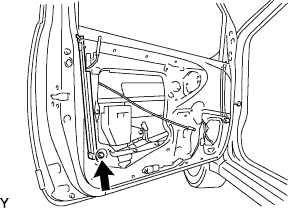
Install the front door rear lower frame sub-assembly with the bolt.
- Torque:
- 6.1 N*m { 62 kgf*cm, 54 in.*lbf }
-
-
INSTALL FRONT DOOR FRONT LOWER FRAME SUB-ASSEMBLY
-
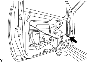
Install the bolt and front door front lower frame sub-assembly.
- Torque:
- 6.1 N*m { 62 kgf*cm, 54 in.*lbf }
-
-
INSTALL FRONT DOOR WINDOW REGULATOR SUB-ASSEMBLY
-
Install the front door window regulator sub-assembly with the 3 nuts.
- Torque:
- 7.0 N*m { 71 kgf*cm, 62 in.*lbf }
Note
Do not drop the front door window regulator sub-assembly as it may be damaged.
-
Connect the connector.
-
-
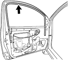
INSTALL FRONT DOOR GLASS SUB-ASSEMBLY
-
Install the front door glass sub-assembly with the 2 bolts.
- Torque:
- 2.8 N*m { 29 kgf*cm, 25 in.*lbf }
Note
Do not damage the front door glass.
-
Install the hole plug.
-
-
INSTALL FRONT DOOR GLASS RUN
-
Install the front door glass run.
-
-
INSTALL FRONT DOOR GLASS INNER WEATHERSTRIP ASSEMBLY
-
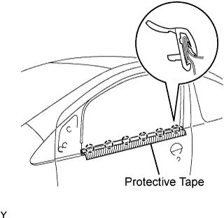
INSTALL FRONT DOOR GLASS OUTER WEATHERSTRIP ASSEMBLY (for 5 Door)
-
Engage the 5 claws and install the front door belt moulding.
-
Remove the protective tape.
-
-
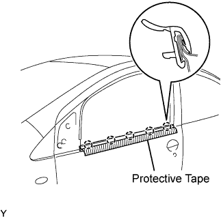
INSTALL FRONT DOOR GLASS OUTER WEATHERSTRIP ASSEMBLY (for 3 Door)
-
Engage the 6 claws and install the front door belt moulding.
-
Remove the protective tape.
-
-
INSTALL FRONT DOOR SERVICE HOLE COVER
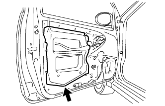
-
Apply butyl tape to the door.
-
Install a new front door service hole cover.
Tech Tips
Remove all wrinkles or folds when attaching the front door service hole cover.
-
-
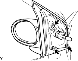
INSTALL OUTER REAR VIEW MIRROR ASSEMBLY
-
Install the outer rear view mirror assembly LH with the 3 screws.
- Torque:
- 7.0 N*m { 71 kgf*cm, 62 in.*lbf }
Note
-
Do not tighten the screws to more than the specified torque.
-
Before tightening the screws to the specified torque, provisionally tighten the screws by hand to fit the threads. Do not remove and reinstall the screws more than twice, when reusing a mirror.
-
-
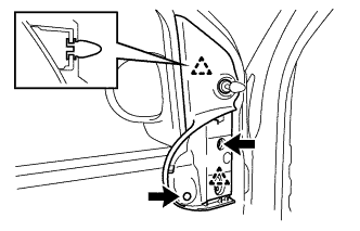
INSTALL FRONT DOOR LOWER FRAME BRACKET GARNISH
-
Engage the 2 clips and install the front door lower frame bracket garnish.
-
Install the 2 screws.
-
-
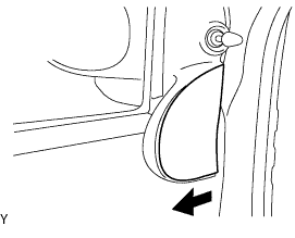
INSTALL FRONT DOOR FRONT LOWER FRAME UPPER COVER
-
Install the front door front lower frame upper cover in the direction shown in the illustration.
-
-
INSTALL FRONT DOOR TRIM BOARD SUB-ASSEMBLY (for 5 Door)
-
Connect the connector.
-
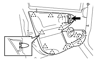
Engage the 13 clips and install the front door trim board sub-assembly.
-
Install the screw.
-
-
INSTALL FRONT DOOR TRIM BOARD SUB-ASSEMBLY (for 3 Door)
-
Connect the connector.
-
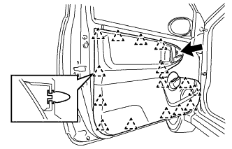
Engage the 15 clips and install the front door trim board sub-assembly.
-
Install the screw.
-
-
INSTALL FRONT ARMREST UPPER BASE PANEL
-
Connect the connector.
-
Engage the 3 claws and install the front armrest upper base panel.
-
-
INSTALL ASSIST GRIP ASSEMBLY
-
Engage the 4 claws and install the assist grip assembly.
-
Install the 2 screws.
-
-
INSTALL DOOR ASSIST GRIP COVER
-
Engage the 2 claws and install the door assist grip cover.
-
-
CONNECT CABLE TO NEGATIVE BATTERY TERMINAL
- Torque:
- 5.4 N*m { 55 kgf*cm, 48 in.*lbf }