WIRELESS DOOR LOCK CONTROL SYSTEM Only Wireless Door Lock Control Function does not Operate
DESCRIPTION
The door control with receiver ECU receives a signal from the transmitter. Then, the door control with receiver ECU controls the door operation by sending LOCK/UNLOCK signals to the appropriate door lock actuator.
WIRING DIAGRAM
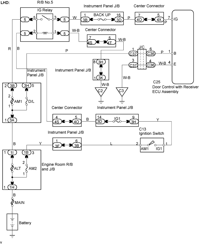
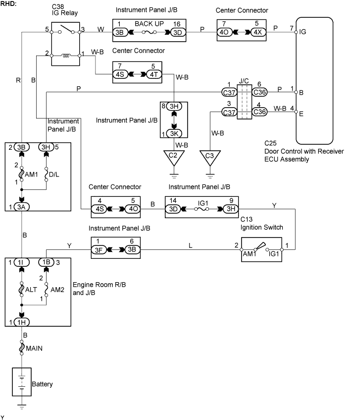
INSPECTION PROCEDURE
PROCEDURE
-
CHECK WIRELESS DOOR LOCK CONTROL FUNCTIONS
-
Check the wireless door lock functions by operating the transmitter switch.
Tech Tips
When the wireless door LOCK/UNLOCK operation function normally, it can be assumed that the transmitter signal is being properly input to the door control with receiver ECU.
NG 
REPLACE TRANSMITTER BATTERY Click here
OK 
NORMAL
-
-
REPLACE TRANSMITTER BATTERY
-
After replacing the transmitter battery with a new or correctly functioning one, check that the doors can be locked and unlocked by using the transmitter LOCK/UNLOCK switch.
OK Doors can be locked and unlocked with transmitter.
NG
CHECK WIRELESS DOOR LOCK FUNCTIONS (STANDARD OPERATION) Click here
OK
END
-
-
CHECK WIRELESS DOOR LOCK FUNCTIONS (STANDARD OPERATION)
-
Check standard LOCK/UNLOCK switch operation.
Note
Standardised test procedure: press the transmitter switch for 1 second, directing the beam at the driver side door outside handle from a distance of 1 m (3.28 ft). The transmitter should be pointed directly at the door handle, i.e. at a 90°angle to the vehicle body.
NG
CONFIRM HAZARD LAMPS ON Click here
OK
REPLACE DOOR CONTROL TRANSMITTER ASSEMBLY
-
-
CONFIRM HAZARD LAMPS ON
-
Check that the hazard lamps come on when push the hazard switch.
OK Hazard lamps come on.
OK
SWITCH TO SELF-DIAGNOSTIC MODE Click here
NG 
-
-
REPAIR OR REPLACE LIGHTING SYSTEM
NEXT
-
SWITCH TO SELF-DIAGNOSTIC MODE
-
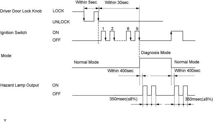
Switch to self-diagnostic mode by operating the ignition key cylinder.
-
Open the driver side door.
-
Put the vehicle into its initial condition Click here.
-
Insert the key into the ignition key cylinder and leave it in the LOCK position.
-
Push the driver door lock knob down to the LOCK position.
-
Perform the following operations within 5 seconds:
-
Pull the driver lock knob up to the UNLOCK position.
-
Push it down to the LOCK position.
-
Pull it up to the UNLOCK position again.
-
-
Within 30 seconds of the completion of step (4) above, perform the following operation 9 times:
-
turn the ignition switch ON and then the LOCK positions.
Note
When the change to self-diagnostic mode is unsuccessful, the system returns to normal mode.
Tech Tips
-
Self-diagnostic mode is terminated if the ignition switch is turned to the ON position after step (6) above.
-
Do not lock or unlock any doors during self-diagnostic mode.
-
-
-
Check that the system has switched to self-diagnostic mode by checking the blinking frequency of the hazard lamps.
OK The hazard lamps output should be as shown in the illustration.
NG
CHECK HARNESS AND CONNECTOR (DOOR CONTROL WITH RECEIVER ECU - BATTERY AND BODY GROUND) Click here
OK
-
-
CONDUCT CHECK IN SELF-DIAGNOSTIC MODE
-
Remove the key.
-
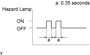
Inspect the diagnosis outputs when the door control transmitter switch is held down. The diagnosis outputs can be checked through the outputs of the hazard lamps.
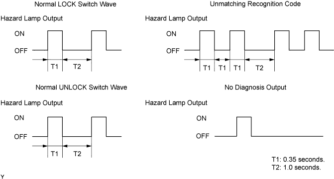
Result Result Proceed to Unmatching recognition code output and hazard lamps stay ON. A Normal waves (hazard lamps blinking) for LOCK and UNLOCK switches output. B No diagnosis outputs present and hazard lamps OFF. C
B 
REPLACE DOOR CONTROL WITH RECEIVER ECU ASSEMBLY
C
CHECK RESPONSE OF DOOR CONTROL WITH RECEIVER ECU ASSEMBLY Click here
A
-
-
REGISTER RECOGNITION CODE
-
Check that the system can switch to rewrite mode or add mode and a recognition code can be registered. Click here
OK Recognition code can be registered.
NG
REPLACE DOOR CONTROL WITH RECEIVER ECU ASSEMBLY
OK
NORMAL
-
-
CHECK RESPONSE OF DOOR CONTROL WITH RECEIVER ECU ASSEMBLY
-
Prepare a new or correctly functioning door control transmitter switch for the same vehicle model. Press and hold a switch on the transmitter and check that an unmatching recognition code is output.
OK Unmatching recognition code is output.
NG
CHECK HARNESS AND CONNECTOR (DOOR CONTROL WITH RECEIVER ECU - BATTERY AND BODY GROUND) Click here
OK
REPLACE DOOR CONTROL TRANSMITTER ASSEMBLY
-
-
CHECK HARNESS AND CONNECTOR (DOOR CONTROL WITH RECEIVER ECU - BATTERY AND BODY GROUND)
-
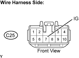
Disconnect the C25 door control with receiver ECU connector.
-
Measure the voltage and resistance.
Standard Voltage Tester Connection Switch Condition Specified Condition C25-1 (B) - Body ground Constant 10 to 14V C25-7 (IG) - Body ground Ignition switch ON 10 to 14V C25-7 (IG) - Body ground Ignition switch OFF Below 1V Standard Resistance Tester Connection Switch Condition Specified Condition C25-4 (E) - Body ground Constant Below 1 Ω -
Reconnect the door control with receiver ECU connector.
NG
REPAIR OR REPLACE HARNESS OR CONNECTOR
OK
REPLACE DOOR CONTROL WITH RECEIVER ECU ASSEMBLY
-