WIRELESS DOOR LOCK CONTROL SYSTEM TERMINALS OF ECU

-
CHECK DOOR CONTROL WITH RECEIVER ECU ASSEMBLY
-
Disconnect the C25 door control with receiver ECU connector.
-
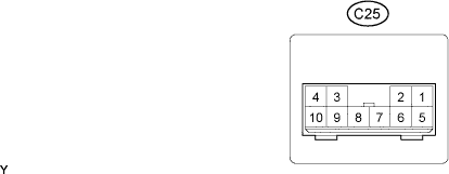
Measure the voltage and resistance of the wire harness side connector.
Standard: Symbols (Terminal No) Wiring Color Terminal Description Condition Specified Condition C25-1 (B) - Body ground P - Body ground +B power supply Always 10 to 14V C25-7 (IG) - Body ground P - Body ground Ignition power supply Ignition Switch OFF Below 1V C25-7 (IG) - Body ground P - Body ground Ignition power supply Ignition Switch ON 10 to 14V C25-4 (E) - Body ground W-B - Body ground Ground Always Below 1Ω C25-10 (DCTY) - Body ground R - Body ground Door courtesy lamp switch signal input Driver side door closed 10 KΩ or higher C25-10 (DCTY) - Body ground R - Body ground Door courtesy lamp switch signal input Driver side door open Below 1Ω If the result is not as specified, there may be a malfunction of the wire harness.
-
Reconnect the door control with receiver ECU connector.
-
Measure the voltage.
Standard: Symbols (Terminal No) Wiring Color Terminal Description Condition Specified Condition C25-5 (HAZ) - Body ground Y - Body ground Hazard warning lamp driver Answer-back OFF 10 to 14V C25-5 (HAZ) - Body ground Y - Body ground Hazard warning lamp driver Answer-back ON Pulse generation If the result is not as specified, there may be a malfunction of the door control with receiver ECU assembly.
-