POWER DOOR LOCK CONTROL SYSTEM All Doors cannot be Locked / Unlocked Simultaneously
DESCRIPTION
The door control with receiver ECU activates the door lock actuator with switch signals from the driver side front door lock actuator.
WIRING DIAGRAM
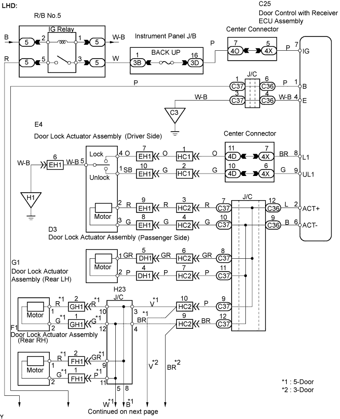
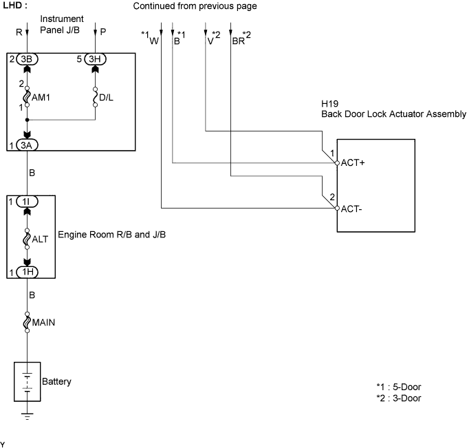
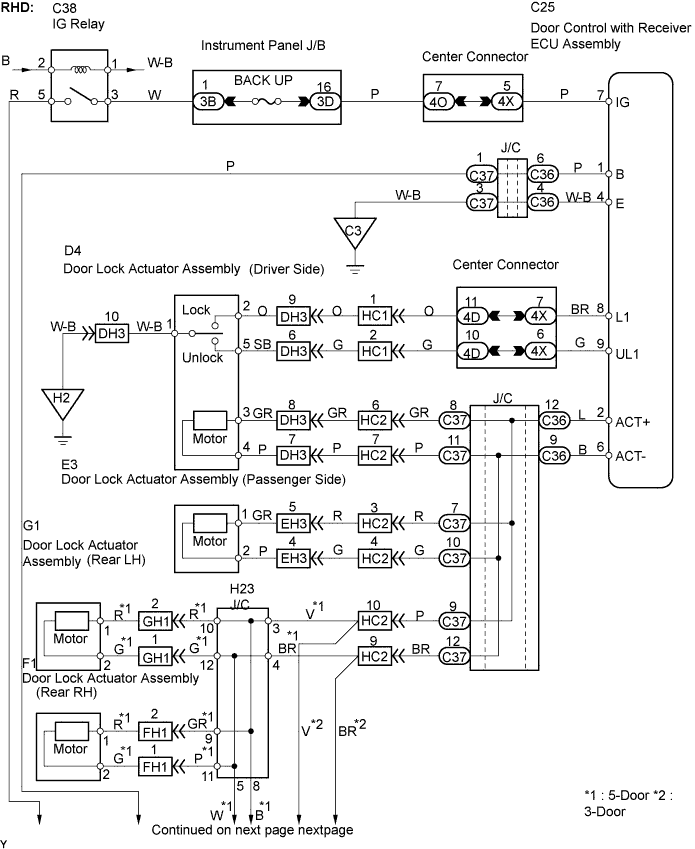
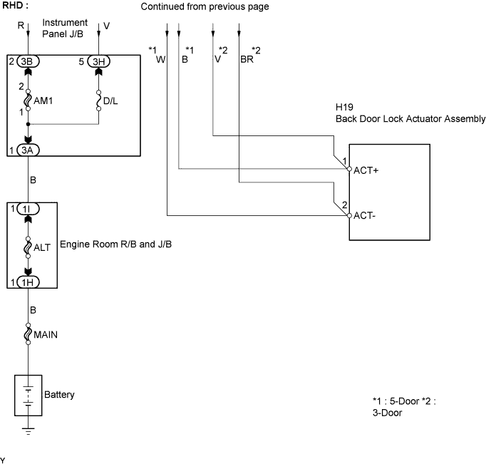
INSPECTION PROCEDURE
Tech Tips
-
All doors can be locked/unlocked simultaneously using the following items:
-
Door lock knob linked with driver side door lock
-
Door key cylinder linked with driver side door lock (key operation)
-
If all the doors cannot be locked/unlocked simultaneously, proceed to the next step according to the malfunctioning part shown in the table below.
Malfunctioning Part Proceed to All doors cannot be locked/unlocked Step 1 Only driver door cannot be locked/unlocked Step 5 Only passenger door cannot be locked/unlocked Step 6 Only rear LH door cannot be locked/unlocked Step 7 Only rear RH door cannot be locked/unlocked Step 8 Only back door cannot be locked/unlocked Step 9
PROCEDURE
-
INSPECT FUSE (D/L, BACK UP)
-
Remove the D/L and BACK UP fuses from the driver side J/B.
-
Measure the resistance.
Standard Resistance Below 1Ω -
Reinstall the D/L and BACK UP fuses.
NG 
CHECK FOR SHORT IN ALL HARNESSES AND CONNECTORS CONNECTED TO FUSE AND REPLACE FUSE
OK 
-
-
CHECK HARNESS AND CONNECTOR (DOOR CONTROL WITH RECEIVER ECU - BATTERY AND BODY GROUND)
-
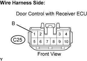
Disconnect the C25 door control with receiver ECU connector.
-
Measure the voltage and resistance of the wire harness side connector.
Standard Voltage Tester Connection Specified Condition C25-1 (B) - Body ground 10 to 14 V Standard Resistance Tester Connection Specified Condition C25-4 (E) - Body ground Below 1 Ω -
Reconnect the door control with receiver ECU connector.
NG
REPAIR OR REPLACE HARNESS OR CONNECTOR
OK
-
-
INSPECT FRONT DOOR LOCK ACTUATOR ASSEMBLY (DRIVER SIDE)
-
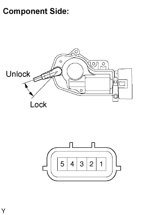
Remove the front door lock actuator.
-
Measure the resistance .
Standard Resistance(LHD) Tester Connection Switch Condition Specified Condition 1 - 5 Unlock Below 1 Ω 1 - 5, 4 - 5 OFF 10 kΩ or higher 4 - 5 Lock Below 1 Ω Standard Resistance(RHD) Tester Connection Switch Condition Specified Condition 1 - 2 Lock Below 1 Ω 1 - 2, 1 - 5 OFF 10 kΩ or higher 1 - 5 Unlock Below 1 Ω -
Reinstall the front door lock actuator.
NG
REPLACE FRONT DOOR LOCK ACTUATOR ASSEMBLY (DRIVER SIDE)
OK
-
-
CHECK HARNESS AND CONNECTOR (FRONT DOOR LOCK ACTUATOR - DOOR CONTROL ECU AND BODY GROUND)
-
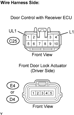
Disconnect the E4 or D4 front door lock actuator connector.
-
Disconnect the C25 door control with receiver ECU connector.
-
Measure the resistance of the wire harness side connectors.
Standard Resistance(LHD) Tester Connection Specified Condition C25-8 (L1)- E4-4 Below 1 Ω C25-9 (UL1)- E4-1 Below 1 Ω E4-5 - Body ground Below 1 Ω Standard Resistance(RHD) Tester Connection Specified Condition C25-8 (L1)- D4-2 Below 1 Ω C25-9 (UL1)- D4-5 Below 1 Ω D4-1 - Body ground Below 1 Ω -
Reconnect the front door lock actuator connector.
-
Reconnect the door control with receiver ECU connector.
NG
REPAIR OR REPLACE HARNESS OR CONNECTOR
OK 
REPLACE DOOR CONTROL WITH RECEIVER ECU ASSEMBLY
-
-
CHECK HARNESS AND CONNECTOR (DOOR CONTROL ECU - FRONT DOOR LOCK ACTUATOR (DRIVER SIDE))
-
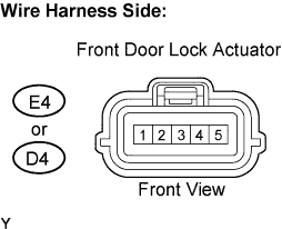
Disconnect the E4 or D4 front door lock actuator connector.
-
Measure the voltage of the wire harness side connectors.
Standard Voltage(LHD) Tester Connection Condition Specified Condition E4-2 - Body ground Door lock control switch (driver side door lock knob or key cylinder) UNLOCK to LOCK 10 to 14V E4-3 - Body ground Door lock control switch (driver side door lock knob or key cylinder) LOCK to UNLOCK 10 to 14V Standard Voltage(RHD) Tester Connection Condition Specified Condition D4-3 - Body ground Door lock control switch (driver side door lock knob or key cylinder) UNLOCK to LOCK 10 to 14V D4-4 - Body ground Door lock control switch (driver side door lock knob or key cylinder) LOCK to UNLOCK 10 to 14V -
Reconnect the front door lock actuator connector.
NG
REPAIR OR REPLACE HARNESS OR CONNECTOR
OK
REPLACE FRONT DOOR LOCK ACTUATOR ASSEMBLY (DRIVER SIDE)
-
-
CHECK HARNESS AND CONNECTOR (DOOR CONTROL ECU - FRONT DOOR LOCK ACTUATOR (PASSENGER SIDE))
-
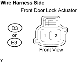
Disconnect the D3 or E3 front door lock actuator connector.
-
Measure the voltage of the wire harness side connectors.
Standard Voltage(LHD) Tester Connection Condition Specified Condition D3-1 - Body ground Door lock control switch (driver side door lock knob or key cylinder) UNLOCK to LOCK 10 to 14V D3-2 - Body ground Door lock control switch (driver side door lock knob or key cylinder) LOCK to UNLOCK 10 to 14V Standard Voltage(RHD) Tester Connection Condition Specified Condition E3-1 - Body ground Door lock control switch (driver side door lock knob or key cylinder) UNLOCK to LOCK 10 to 14V E3-2 Body ground Door lock control switch (driver side door lock knob or key cylinder) LOCK to UNLOCK 10 to 14V -
Reconnect the front door lock actuator connector.
NG
REPAIR OR REPLACE HARNESS OR CONNECTOR
OK
REPLACE FRONT DOOR LOCK ACTUATOR ASSEMBLY (PASSENGER SIDE)
-
-
CHECK HARNESS AND CONNECTOR (DOOR CONTROL WITH RECEIVER ECU - REAR DOOR LOCK ACTUATOR LH)
-
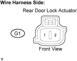
Disconnect the G1 rear door lock actuator connector.
-
Measure the voltage of the wire harness side connectors.
Standard Voltage Tester Connection Condition Specified Condition G1-1 - Body ground Door lock control switch (driver side door lock knob or key cylinder) UNLOCK to LOCK 10 to 14V G1-2 Body ground Door lock control switch (driver side door lock knob or key cylinder) LOCK to UNLOCK 10 to 14V -
Reconnect the rear door lock actuator connector.
NG
REPAIR OR REPLACE HARNESS OR CONNECTOR
OK
REPLACE REAR DOOR LOCK ACTUATOR ASSEMBLY LH
-
-
CHECK HARNESS AND CONNECTOR (DOOR CONTROL WITH RECEIVER ECU - REAR DOOR LOCK ACTUATOR RH)
-
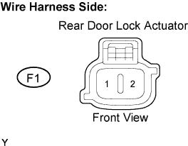
Disconnect the F1 rear door lock actuator connector.
-
Measure the voltage of the wire harness side connectors.
Standard Voltage Tester Connection Condition Specified Condition F1-1 - Body ground Door lock control switch (driver side door lock knob or key cylinder) UNLOCK to LOCK 10 to 14V F1-2 - Body ground Door lock control switch (driver side door lock knob or key cylinder) LOCK to UNLOCK 10 to 14V -
Reconnect the rear door lock actuator connector.
NG
REPAIR OR REPLACE HARNESS OR CONNECTOR
OK
REPLACE REAR DOOR LOCK ACTUATOR ASSEMBLY RH
-
-
CHECK HARNESS AND CONNECTOR (DOOR CONTROL WITH RECEIVER ECU - BACK DOOR LOCK ACTUATOR)
-
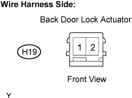
Disconnect the H19 back door lock actuator connector.
-
Measure the voltage of the wire harness side connector.
Standard Voltage Tester Connection Condition Specified Condition H19-1 - Body ground Door lock control switch (driver side door lock knob or key cylinder) UNLOCK to LOCK 10 to 14V H19-2 - Body ground Door lock control switch (driver side door lock knob or key cylinder) LOCK to UNLOCK 10 to 14V -
Reconnect the back door lock actuator connector.
NG
REPAIR OR REPLACE HARNESS OR CONNECTOR
OK
REPLACE BACK DOOR LOCK ACTUATOR ASSEMBLY
-