METER / GAUGE SYSTEM Malfunction in Water Temperature Warning Light
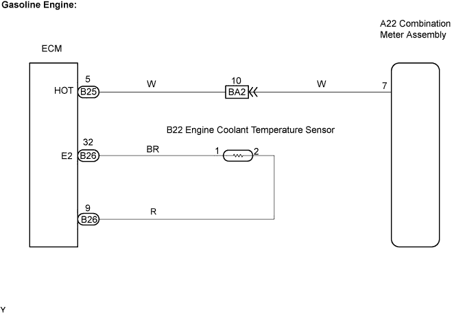
WIRING DIAGRAM
INSPECTION PROCEDURE
PROCEDURE
-
READ VALUE OF INTELLIGENT TESTER (ENGINE COOLANT TEMPERATURE)
-
Connect an intelligent tester to the DLC3.
-
Start the engine and turn the intelligent tester ON.
-
On the intelligent tester, select the following menu items: Powertrain / Engine and ECT / Data List / Coolant Temp.
-
Read the value displayed on the tester.
OK Between 75°C and 97°C (167°F and 207°F) with the engine warmed up.
NG 
GO TO ENGINE CONTROL SYSTEM
OK 
-
-
INSPECT COMBINATION METER ASSEMBLY
-
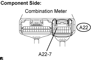
Check the meter indicator conditions.
OK Wire Connection Condition Specified Condition A22-7 - Body ground Short circuit
(Ignition switch ON)
High engine coolant temperature indicator ON Tech Tips
This inspection creates an intentional short circuit between the connector terminal and body ground, to check the meter indicator operation.
OK 
CHECK HARNESS AND CONNECTOR (COMBINATION METER ASSEMBLY - ECM) Click here
NG 
REPLACE COMBINATION METER ASSEMBLY
-
-
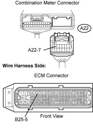
CHECK HARNESS AND CONNECTOR (COMBINATION METER ASSEMBLY - ECM)
-
Gasoline Engine:
-
Disconnect the A22 combination meter connector.
-
Disconnect the B25 ECM connector.
-
Measure the resistance.
Standard Resistance Tester Connection Specified Condition A22-7 - B25-5 Below 1 Ω A22-7 or B25-5 - Body ground 10 kΩ or higher -
Reconnect the ECM connector.
-
Reconnect the combination meter connector.
-
-
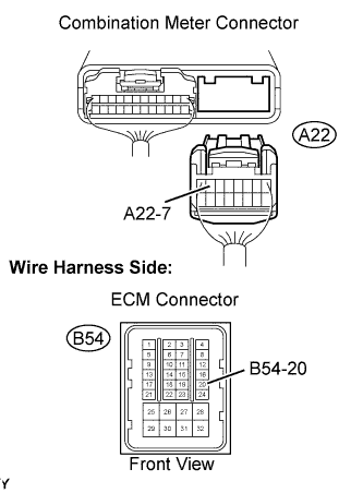
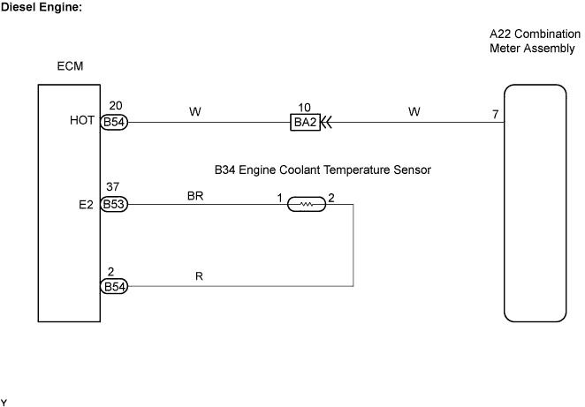
Diesel Engine:
-
Disconnect the A22 combination meter connector.
-
Disconnect the B54 ECM connector.
-
Measure the resistance.
Standard Resistance Tester Connection Specified Condition A22-7 - B54-20 Below 1 Ω A22-7 or B54-20 - Body ground 10 kΩ or higher -
Reconnect the ECM connector.
-
Reconnect the combination meter connector.
-
NG
REPAIR OR REPLACE HARNESS OR CONNECTOR
OK
REPLACE ECM
-