METER / GAUGE SYSTEM Fuel Gauge Malfunction
WIRING DIAGRAM
INSPECTION PROCEDURE
PROCEDURE
-
INSPECT HARNESS AND CONNECTOR
-
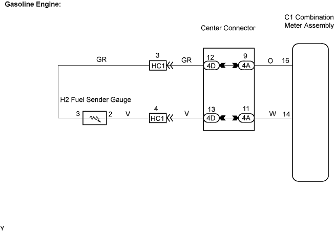
Gasoline Engine:
-
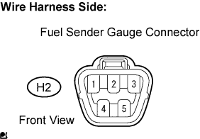
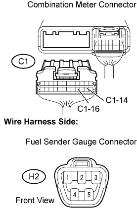
Disconnect the H2 fuel sender gauge connector.
-
Check the meter indicator conditions.
Result Wire Connection Condition Specified Condition 2 - 3 Short circuit
(Ignition switch ON)
Fuel gauge indicates F or more (Combination meter) Tech Tips
This inspection creates an intentional short circuit between the connector terminals, to check the meter indicator operation.
Note
Perform the check quickly (within less than 10 seconds).
Standard Voltage Tester Connection Condition Specified Condition 3 - Body ground Ignition switch ON 4 to 7 V -
Measure the voltage.
-
Reconnect the fuel sender gauge connector.
-
-
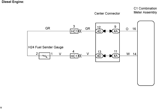
Diesel Engine:
-
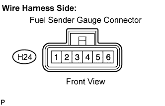
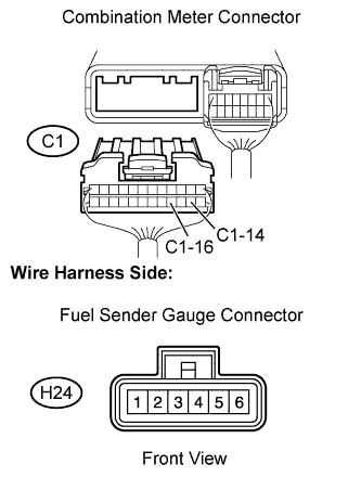
Disconnect the H24 fuel sender gauge connector.
-
Check the meter indicator conditions.
Result Wire Connection Condition Specified Condition 1 - 2 Short circuit
(Ignition switch ON)
Fuel gauge indicates F or more (Combination meter) Tech Tips
This inspection creates an intentional short circuit between the connector terminals, to check the meter indicator operation.
Note
Perform the check quickly (within less than 10 seconds).
-
Measure the voltage.
Standard Voltage Tester Connection Condition Specified Condition 2 - Body ground Ignition switch ON 4 to 7 V -
Reconnect the fuel sender gauge connector.
-
NG 
CHECK HARNESS AND CONNECTOR (FUEL SENDER GAUGE ASSEMBLY - COMBINATION METER ASSEMBLY) Click here
OK 
-
-
INSPECT FUEL SENDER GAUGE ASSEMBLY
-
Gasoline Engine:
-
Remove the fuel sender gauge assembly.
-
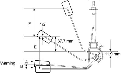
Check that the float position is between E and F.
-
Measure the resistance between terminals 2 and 3 of the fuel sender gauge connector.
Standard Resistance Float Level Float Position [mm in.]) Specified Condition F 73.6 (2.9) to 78.6 (3.1) 12.0 Ω to 18.0 Ω 1/2 1.3 (0.05) 199.0 Ω to 217.0 Ω Warning A 20.4 (0.80) 358.7 Ω to 386.7 Ω Warning B 10.4 (0.41) 376.4 Ω to 406.4 Ω E 76.3 (3.09) to 81.3 (3.11) 405.0 Ω to 415.0 Ω -
Reinstall the fuel sender gauge assembly.
-
-
Diesel Engine:
-
Disconnect the H24 fuel sender gauge connector.
-
Measure the resistance between terminals 1 and 2 of the fuel sender gauge connector.
Standard Resistance Float Level Fuel Quantity (liters [US qts, Imp, qts]) Specified Condition F 33.70 (35.61, 29.66) 35.0 Ω to 65.0 Ω 1/2 17.50 (18.49, 15.40) 161.6 Ω to 191.6Ω Warning A 5.25 (5.55, 4.62) 273.0 Ω to 303.0 Ω Warning B 3.50 (3.70, 3.08) 293.0 Ω to 323.0 Ω E 0.38 (0.40, 0.33) 335.0 Ω to 365.0 Ω -
Reconnect the fuel sender gauge connector.
-
NG 
REPLACE FUEL SENDER GAUGE ASSEMBLY
OK 
REPLACE COMBINATION METER ASSEMBLY
-
-
CHECK HARNESS AND CONNECTOR (FUEL SENDER GAUGE ASSEMBLY - COMBINATION METER ASSEMBLY)
-
Gasoline Engine:
-
Disconnect the C1 combination meter connector.
-
Disconnect the H2 fuel sender gauge connector.
-
Measure the resistance.
Standard Resistance Tester Connection Specified Condition C1-14 - H2-2 Below 1 Ω C1-16 - H2-3 Below 1 Ω C1-14 or H2-2 - Body ground 10 kΩ or higher C1-16 or H2-3 - Body ground 10 kΩ or higher -
Reconnect the fuel sender gauge connector.
-
Reconnect the combination meter connector.
-
-
Diesel Engine:
-
Disconnect the C1 combination meter connector.
-
Disconnect the H24 fuel sender gauge connector.
-
Measure the resistance.
Standard Resistance Tester Connection Specified Condition C1-14 - H24-1 Below 1 Ω C1-16 - H24-2 Below 1 Ω C1-14 or H24-1 - Body ground 10 kΩ or higher C1-16 or H24-2 - Body ground 10 kΩ or higher -
Reconnect the fuel sender gauge connector.
-
Reconnect the combination meter connector.
-
NG
REPAIR OR REPLACE HARNESS OR CONNECTOR
OK
REPLACE COMBINATION METER ASSEMBLY
-