METER / GAUGE SYSTEM Tachometer Malfunction
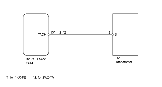
WIRING DIAGRAM
INSPECTION PROCEDURE
PROCEDURE
-
INSPECT TACHOMETER
-
Disconnect the C2 tachometer connector.
-
Start the engine.
-
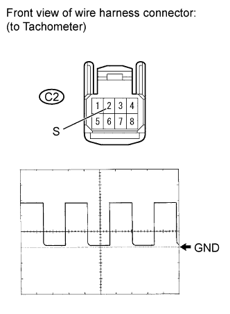
Check the voltage with the engine idling.
OK Tester Connection Specified Condition C2-2 (S) - Body ground Voltage generated intermittently OK As shown in the illustration. -
Reconnect the tachometer connector.
NG 
READ VALUE USING INTELLIGENT TESTER (ENGINE SPEED) Click here
OK 
REPLACE TACHOMETER Click here
-
-
READ VALUE USING INTELLIGENT TESTER (ENGINE SPEED)
-
Connect an intelligent tester to the DLC3.
-
Start the engine and turn the intelligent tester ON.
-
Enter the following menus: Powertrain / Engine and ECT / Data List / Engine SPD.
-
Read the value displayed on the tester.
OK The engine speed displayed on the tester is approximately equal to the actual engine speed. Result Result Proceed to OK A NG (for 1KR-FE with Electronic Throttle Control System) B NG (for 1KR-FE without Electronic Throttle Control System) C NG (2WZ-TV) D
B 
GO TO ENGINE CONTROL SYSTEM Click here
C
GO TO ENGINE CONTROL SYSTEM Click here
D
GO TO ENGINE CONTROL SYSTEM Click here
A 
-
-
CHECK HARNESS AND CONNECTOR (TACHOMETER - ECM)
-
Disconnect the C2 tachometer connector.
-
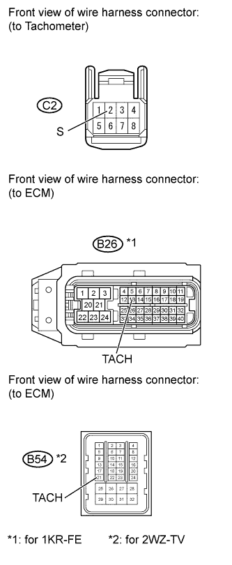
Disconnect the B26 or B54 ECM connector.
-
Measure the resistance according to the value(s) in the table below.
Standard Resistance for 1KR-FE Tester Connection Condition Specified Condition C2-2 (S) - B26-13 (TACH) Always Below 1 Ω C2-2 (S) or B26-13 (TACH) - Body ground Always 10 kΩ or higher for 2WZ-TV Tester Connection Condition Specified Condition C2-2 (S) - B54-21 (TACH) Always Below 1 Ω C2-2 (S) or B54-21 (TACH) - Body ground Always 10 kΩ or higher -
Reconnect the ECM connector.
-
Reconnect the tachometer connector.
NG
REPAIR OR REPLACE HARNESS OR CONNECTOR
OK
REPLACE TACHOMETER Click here
-