METER / GAUGE SYSTEM Tachometer Malfunction
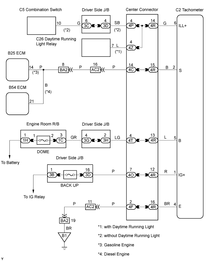
WIRING DIAGRAM
INSPECTION PROCEDURE
PROCEDURE
-
READ VALUE USING INTELLIGENT TESTER (ENGINE SPEED)
-
Connect an intelligent tester to the DLC3.
-
Start the engine and turn the intelligent tester ON.
-
On the intelligent tester, select the following menu items: Powertrain / Engine and ECT / Data List / Engine SPD.
-
Read the value displayed on the tester.
OK The engine speed displayed on the tester is approximately equal to the actual engine speed.
NG 
GO TO ENGINE CONTROL SYSTEM
OK 
-
-
INSPECT TACHOMETER
-
Disconnect the C2 tachometer connector.
-
Start the engine.
-
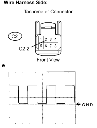
Check the voltage with the engine idling.
Standard Voltage Tester Connection Specified Condition C2-2 - Body ground Voltage generated intermittently OK As shown in the illustration. -
Reconnect the tachometer connector.
NG
REPLACE TACHOMETER
OK
-
-
CHECK FUSE (BUCK UP, DOME)
-
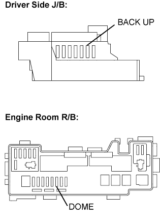
Remove the BACK UP fuse from the driver side J/B.
-
Remove the DOME fuse from the engine room R/B.
-
Measure the resistance.
Standard Resistance Below 1 Ω -
Reinstall the fuses.
NG
INSPECT FOR SHORT CIRCUIT IN HARNESS AND ALL COMPONENTS CONNECTED TO FUSE
OK
-
-
CHECK HARNESS AND CONNECTOR (TACHOMETER-ECM)
-
Gasoline Engine:
-
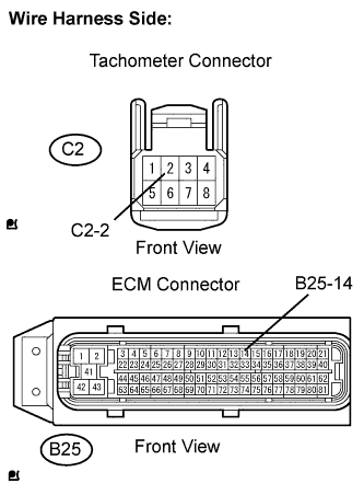
Disconnect the C2 tachometer connector.
-
Disconnect the B25 ECM connector.
-
Measure the resistance.
Standard Resistance Tester Connection Specified Condition C2-2 - B25-14 Below 1 Ω C2-2 or B25-14 - Body ground 10 kΩ or higher -
Reconnect the ECM connector.
-
Reconnect the tachometer connector.
-
-
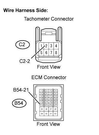
Diesel Engine:
-
Disconnect the C2 tachometer connector.
-
Disconnect the B54 ECM connector.
-
Measure the resistance.
Standard Resistance Tester Connection Specified Condition C2-2 - B54-21 Below 1 Ω C2-2 or B54-21 - Body ground 10 kΩ or higher -
Reconnect the ECM connector.
-
Reconnect the tachometer connector.
-
NG
REPAIR OR REPLACE HARNESS OR CONNECTOR
OK 
REPLACE TACHOMETER
-