METER / GAUGE SYSTEM Speedometer Malfunction
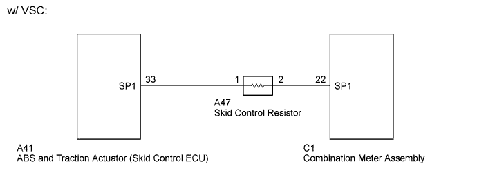
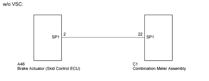
WIRING DIAGRAM
INSPECTION PROCEDURE
PROCEDURE
-
INSPECT COMBINATION METER ASSEMBLY (SPEED SIGNAL)
-
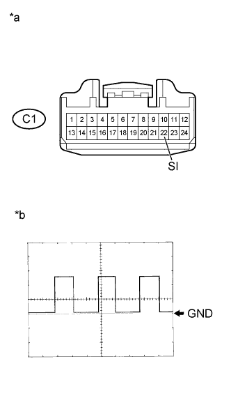
Text in Illustration *a Front view of wire harness connector
(to Combination Meter Assembly)
*b Waveform Disconnect the C1 combination meter assembly connector.
-
Move the shift lever to the neutral position.
-
Jack up the vehicle.
-
Turn the ignition switch to ON.
-
Using an oscilloscope, check the waveform while the wheel is turned slowly.
Item Contents Terminal Connections C1-22 (SI) - Body ground Tester Range 5V/DIV, 20 msec/DIV Vehicle Condition Wheel is turned slowly. OK Waveform is as shown in the illustration. Result Result Proceed to OK A NG (w/ VSC) B NG (w/o VSC) C -
Reconnect the combination meter assembly connector.
B 
CHECK HARNESS AND CONNECTOR (ABS AND TRACTION ACTUATOR (SKID CONTROL ECU) - COMBINATION METER ASSEMBLY) Click here
C
CHECK HARNESS AND CONNECTOR (BRAKE ACTUATOR (SKID CONTROL ECU) - COMBINATION METER ASSEMBLY) Click here
A 
REPLACE COMBINATION METER ASSEMBLY Click here
-
-
CHECK HARNESS AND CONNECTOR (ABS AND TRACTION ACTUATOR (SKID CONTROL ECU) - COMBINATION METER ASSEMBLY)
-
Disconnect the C1 combination meter assembly connector.
-
Disconnect the A41 ABS and traction actuator (skid control ECU) connector.
-
Measure the resistance according to the value(s) in the table below.
Standard Resistance Tester Connection Condition Specified Condition A41-33 (SP1) - C1-22 (SI) Always 19 to 21 Ω A41-33 (SP1) or C1-22 (SI) - Body ground Always 10 kΩor higher -
Reconnect the ABS and traction actuator (skid control ECU) connector.
-
Reconnect the combination meter assembly connector.
NG 
REPAIR OR REPLACE HARNESS OR CONNECTOR
OK
GO TO VEHICLE STABILITY CONTROL SYSTEM Click here
-
-
CHECK HARNESS AND CONNECTOR (BRAKE ACTUATOR (SKID CONTROL ECU) - COMBINATION METER ASSEMBLY)
-
Disconnect the C1 combination meter assembly connector.
-
Disconnect the A46 brake actuator (skid control ECU) connector.
-
Measure the resistance according to the value(s) in the table below.
Standard Resistance Tester Connection Condition Specified Condition A46-2 (SP1) - C1-22 (SI) Always 19 to 21 Ω A46-2 (SP1) or C1-22 (SI) - Body ground Always 10 kΩor higher -
Reconnect the brake actuator (skid control ECU) connector.
-
Reconnect the combination meter assembly connector.
NG
REPAIR OR REPLACE HARNESS OR CONNECTOR
OK
GO TO ANTI-LOCK BRAKE SYSTEM Click here
-