METER / GAUGE SYSTEM Speedometer Malfunction
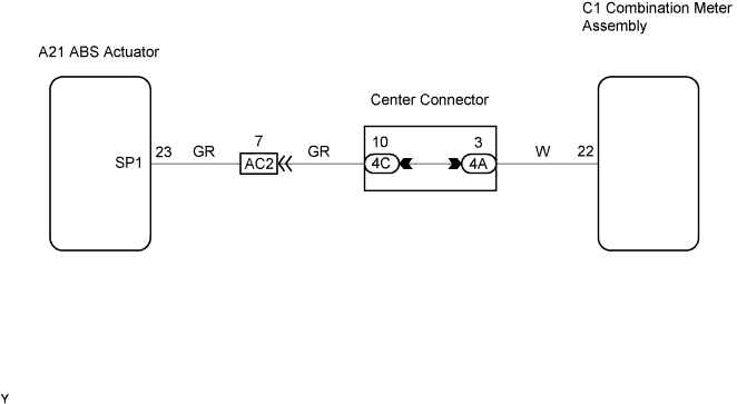
WIRING DIAGRAM
INSPECTION PROCEDURE
PROCEDURE
-
READ VALUE USING INTELLIGENT TESTER II (VEHICLE SPEED)
-
Connect an intelligent tester II to the DLC3.
-
Start the engine and turn the intelligent tester II ON.
-
On the intelligent tester II, select the following menu items: Powertrain / Engine and ECT / Data List / Vehicle SPD.
-
Check the vehicle speed at an engine speed of 2,000 rpm or more while the vehicle is running.
OK The vehicle speed displayed on the tester is approximately equal to the actual vehicle speed.
NG 
GO TO BRAKE SYSTEM
OK 
-
-
INSPECT COMBINATION METER ASSEMBLY
-
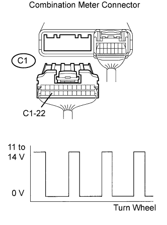
Disconnect the C1 combination meter connector.
-
Shift the transmission gear selector lever to the neutral position.
-
Jack up the vehicle.
-
Turn the ignition switch to the ON position.
-
Check the voltage while the wheel is turning slowly.
Standard Voltage Tester Connection Specified Condition C1-22 - Body ground Voltage generated intermittently Tech Tips
The output voltage should fluctuate up and down as shown in the diagram on the left when the wheel is turning slowly.
OK As shown in the illustration. -
Reconnect the combination meter connector.
OK
REPLACE COMBINATION METER ASSEMBLY
NG
-
-
CHECK HARNESS AND CONNECTOR (SKID CONTROL ECU - COMBINATION METER ASSEMBLY)
-
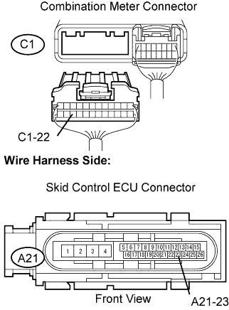
Disconnect the C1 combination meter connector.
-
Disconnect the A21 skid control ECU connector.
-
Measure the resistance.
Standard Resistance Tester Connection Specified Condition A21-23 - C1-22 Below 1 Ω A21-23 or C1-22 - Body ground 10 kΩor higher -
Reconnect the skid control ECU connector.
-
Reconnect the combination meter connector.
OK
CHECK FOR INTERMITTENT PROBLEM
NG 
REPAIR OR REPLACE HARNESS OR CONNECTOR
-