METER / GAUGE SYSTEM Malfunction in Water Temperature Warning Light
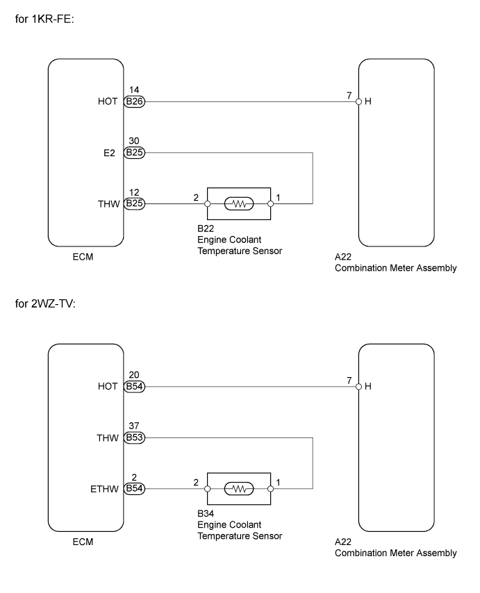
WIRING DIAGRAM
INSPECTION PROCEDURE
PROCEDURE
-
INSPECT COMBINATION METER ASSEMBLY
-
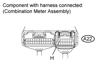
Connect terminals A22-7 (H) and body ground on the wire harness side connector of the combination meter assembly.
-
Turn the ignition switch to ON, and then check the meter indicator conditions.
OK High engine coolant temperature indicator is ON.
NG 
REPLACE COMBINATION METER ASSEMBLY Click here
OK 
-
-
READ VALUE USING INTELLIGENT TESTER (ENGINE COOLANT TEMPERATURE)
-
Connect an intelligent tester to the DLC3.
-
Start the engine and turn the intelligent tester ON.
-
Enter the following menus: Powertrain / Engine and ECT / Data List / Coolant Temp.
-
Read the value displayed on the tester.
Standard Between 75°C and 97°C (167°F and 207°F) with the engine warmed up. Result Result Proceed to OK A NG (for 1KR-FE with Electronic Throttle Control System) B NG (for 1KR-FE without Electronic Throttle Control System) C NG (2WZ-TV) D
B
GO TO ENGINE CONTROL SYSTEM Click here
C
GO TO ENGINE CONTROL SYSTEM Click here
D
GO TO ENGINE CONTROL SYSTEM Click here
A
-
-
CHECK HARNESS AND CONNECTOR (COMBINATION METER ASSEMBLY - ECM)
-
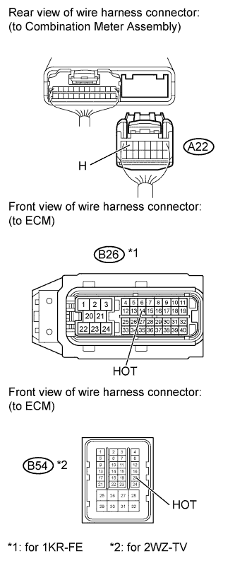
Disconnect the A22 combination meter assembly connector.
-
Disconnect the B26 or B54 ECM connector.
-
Measure the resistance according to the value(s) in the table below.
Standard Resistance for 1KR-FE Tester Connection Condition Specified Condition A22-7 (H) - B26-14 (HOT) Always Below 1 Ω A22-7 (H) or B26-14 (HOT) - Body ground Always 10 kΩ or higher for 2WZ-TV Tester Connection Condition Specified Condition A22-7 (H) - B54-20 (HOT) Always Below 1 Ω 22-7 (H) or B54-20 (HOT) - Body ground Always 10 kΩ or higher Result Result Proceed to NG A OK (for 1KR-FE with Electronic Throttle Control System) B OK (for 1KR-FE without Electronic Throttle Control System) C OK (2WZ-TV) D -
Reconnect the ECM connector.
-
Reconnect the combination meter assembly connector.
B
REPLACE ECM Click here
C
REPLACE ECM Click here
D
REPLACE ECM Click here
A 
REPAIR OR REPLACE HARNESS OR CONNECTOR
-