ENGINE IMMOBILISER SYSTEM, Diagnostic DTC:B2797

| DTC Code | DTC Name |
|---|---|
| B2797 | Communication Malfunction No. 1 |
DESCRIPTION
This DTC is output when a communication error occurs between the transponder key coil and transponder key ECU.
Tech Tips
Noise is found in the communication line.
| DTC No. | DTC Detection Condition | Trouble Areas |
|---|---|---|
| B2797 | Keys positioned too close to each other, or noise occurs in communication line | -Key -Wire harness or connector -Transponder key coil -Transponder key ECU assembly |
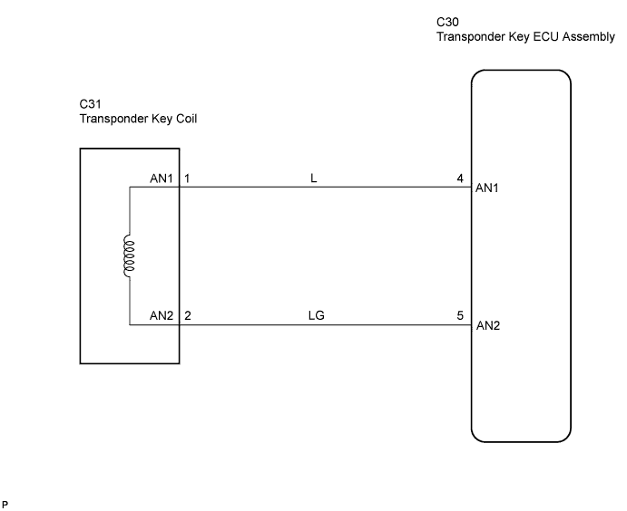
WIRING DIAGRAM
INSPECTION PROCEDURE
PROCEDURE
-
CHECK KEYS
-
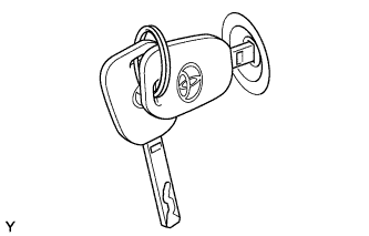
Check whether the ignition key being used is near other ignition keys, as shown in the illustration. Also, check whether the key ring is in contact with the key grip.
Result Result Proceed to Key near other keys and/or key rings in contact with key grip A Key not near other keys and key rings not in contact with key grip B
B 
CHECK WHETHER ENGINE STARTS WITH OTHER KEYS Click here
A 
-
-
CHECK FOR DTCs
-
Separate the keys from each other. Or, remove the key ring.
-
Clear the DTC Click here.
-
Insert a key into the ignition key cylinder. Then turn the key to the ACC position and remove it. Perform this for all the other keys.
-
Check that no DTC is output.
OK No DTC output
OK 
END
NG
-
-
CHECK WHETHER ENGINE STARTS WITH OTHER KEYS
-
Insert the another of the vehicle's keys into the ignition key cylinder.
-
Check that the engine starts with the key.
Note
Prior to inspection, make sure that there are no strong radio wave sources, which may cause communication failures, between the key and coil.
OK Engine starts.
OK
RE-REGISTER OR REPLACE KEY THAT WILL NOT START ENGINE
NG
-
-
CHECK HARNESS AND CONNECTOR (TRANSPONDER KEY ECU ASSEMBLY - TRANSPONDER KEY COIL)
-
Disconnect the C30 transponder key ECU assembly connector.
-
Disconnect the C31 transponder key coil connector.
-
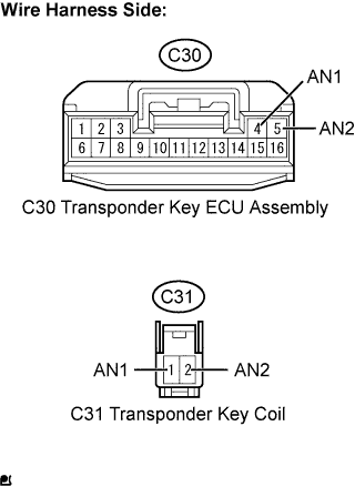
Measure the resistance of the wire harness side connectors.
Standard Resistance Tester Connection Specified Condition C30-4 (AN1) - C31-1 (AN1) Below 1 Ω C30-5 (AN2) - C31-2 (AN2) Below 1 Ω C30-4 (AN1) -or C31-1 (AN1) - Body ground 10 kΩ or higher C30-5 (AN2) -or C31-2 (AN2) - Body ground 10 kΩ or higher -
Reconnect the transponder key coil connector.
-
Reconnect the transponder key ECU assembly connector.
NG
REPAIR OR REPLACE HARNESS OR CONNECTOR
OK
-
-
REPLACE TRANSPONDER KEY COIL
NEXT
-
CHECK OPERATION OF TRANSPONDER KEY COIL
-
After replacing the transponder key coil, check that the engine starts.
OK Engine starts. Tech Tips
Re-register all the keys after replacing the transponder key ECU assembly
NG
REPLACE TRANSPONDER KEY ECU ASSEMBLY
OK 
END
-