ENGINE IMMOBILISER SYSTEM TERMINALS OF ECU

-
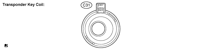
CHECK TRANSPONDER KEY COIL
-
Disconnect the C31 transponder key coil connector.
-
Measure the resistance of the component side connector.
Standard Resistance: Symbols (Terminal No.) Wiring Color Terminal Description Condition Specified Condition AN1(C31-1) - AN2(C31-2) L - LG Transponder key coil Always Below 1 Ω If the result is not as specified, there may be a malfunction in the transponder key coil.
-
-
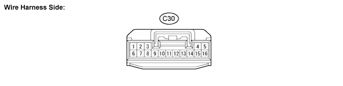
CHECK TRANSPONDER KEY ECU ASSEMBLY
-
Disconnect the C30 transponder key ECU connector.
-
Measure the resistance and voltage of the wire harness side connector.
Standard: Symbols (Terminal No.) Wiring Color Terminal Description Condition Specified Condition IG(C30-2) - GND(C30-16) B - W-B Ignition switch Ignition switch OFF to ON 0 V → 10 to 14 V +B(C30-1) - GND(C30-16) G - W-B Power source Always 10 to 15 V GND(C30-16) - Body ground W-B - Body ground Ground Always Below 1 Ω
-