CURTAIN SHIELD AIRBAG ASSEMBLY (for 5 Door) INSTALLATION

CAUTION:
Some of these service operations affect the SRS airbag system. Be sure to read the precautionary notices concerning the SRS airbag system before servicing Click here.
-
INSTALL CURTAIN SHIELD AIRBAG ASSEMBLY
-
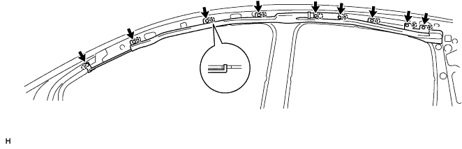
Engage the 9 hooks and install the curtain shield airbag.
-
Tighten the 9 bolts.
- Torque:
- 9.8 N*m { 100 kgf*cm, 7.2 ft.*lbf }
-
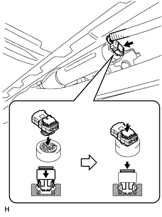
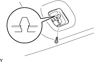
Connect the airbag connector, as shown in the illustration.
-
-
INSTALL ROOF HEADLINING
-
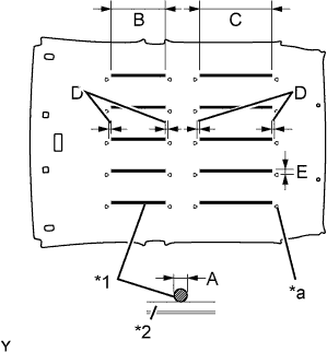
Text in Illustration *1 Adhesive *2 Roof Headlining *a Marking Gently remove the backing sheet and any adhesive remaining on the roof panel.
Tech Tips
It is not necessary to remove the adhesive completely.
-
Apply adhesive (Henkel Terostat 8595N/MT) to a new roof headlining.
Specification Area Measurement A φ6 to 8 mm (0.236 to 0.315 in.) B 290 mm (11.417 in.) C 395 mm (15.551 in.) D 20 to 30 mm (0.787 to 1.181 in.) Note
-
Apply adhesive 20 to 30 mm (0.787 to 1.181 in.) away from the markings placed on the roof headlining.
-
Avoid adhesive accumulation.
-
-
Install the roof headlining onto the vehicle.
-
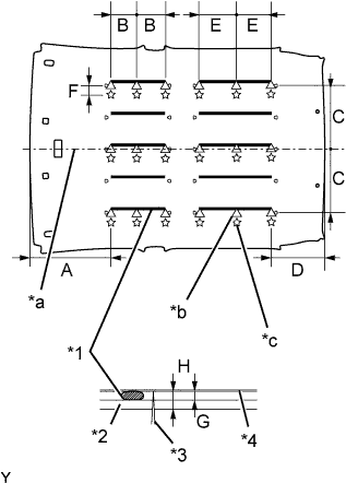
Text in Illustration *1 Adhesive *2 Roof Headlining *3 Needle *4 Roof Panel *a Center *b Push Up Area *c Insert Area Push the roof headlining up to the roof panel until the distance between the roof panel and the backing sheet is less than 4 mm (0.157 in.) at all 18 points shown in the illustration.
Specification Area Measurement A 430 mm (16.929 in.) B 145 mm (5.709 in.) C 335 mm (13.189 in.) D 280 mm (11.024 in.) E 197 mm (7.756 in.) F 20 mm (0.787 in.) G 4 mm or less (0.157 in. or less) H 10 mm or less (0.394 in. or less) Note
-
Be sure to press the roof headlining onto the roof panel with clean hands.
-
Gently and uniformly press the whole roof headlining since pressing it locally could damage it.
-
-
Insert a clean needle into the 18 points shown in the illustration from the roof headlining side, and press the roof headlining until the distance between the roof panel and roof headlining surface is less than 10 mm (0.394 in.).
Note
Do not stick the needle into areas where adhesive is applied, as this could make the roof headlining dirty.
-
Engage the 2 hooks
-
Install the 2 clips.
-
-
INSTALL ROOM LIGHT ASSEMBLY
-
Connect the connector.
-
Engage the 4 claws and install the room light assembly.
-
-
INSTALL VISOR HOLDER
Tech Tips
Use the same procedure for both sides.
-
Engage the claw and install the visor holder.
-
Tighten the screw.
-
-
INSTALL VISOR ASSEMBLY RH
-
Install the visor with the 2 screws.
-
Install the visor into the visor holder.
-
-
INSTALL VISOR ASSEMBLY LH
Tech Tips
Use the same procedure as for the RH side.
-
INSTALL CENTER PILLAR GARNISH UPPER RH
-
Pass the front seat outer belt through the slit of the center pillar garnish upper.
-
Engage the clip and claw, and install the center pillar garnish upper.
-
-
INSTALL CENTER PILLAR GARNISH UPPER LH
Tech Tips
Use the same procedure as for the RH side.
-
INSTALL FRONT SEAT OUTER BELT ASSEMBLY RH
-
Install the lap outer anchor plate of the front seat outer belt with the bolt.
- Torque:
- 42 N*m { 430 kgf*cm, 31 ft.*lbf }
-
-
INSTALL FRONT SEAT OUTER BELT ASSEMBLY LH
Tech Tips
Use the same procedure as for the RH side.
-
INSTALL CENTER PILLAR GARNISH LOWER RH
-
Engage the 2 clips and 3 claws, and install the center pillar garnish lower.
-
-
INSTALL CENTER PILLAR GARNISH LOWER LH
Tech Tips
Use the same procedure as for the RH side.
-
INSTALL ROOF SIDE GARNISH INNER RH
-
Pass the rear seat outer belt through the slit of the roof side garnish inner.
-
Engage the 3 clips and claw, and install the roof side garnish inner.
-
Tighten the screw.
-
Install the clip.
-
-
INSTALL ROOF SIDE GARNISH INNER LH
Tech Tips
Use the same procedure as for the RH side.
-
INSTALL REAR SEAT SIDE GARNISH RH
-
Engage the clip and 6 claws, and install the rear seat side garnish.
-
Install the clip.
-
-
INSTALL REAR SEAT SIDE GARNISH LH
Tech Tips
Use the same procedure as for the RH side.
-
INSTALL REAR SEAT OUTER BELT ASSEMBLY RH
-
Install the lap outer anchor plate of the rear seat outer belt with the bolt.
- Torque:
- 42 N*m { 430 kgf*cm, 31 ft.*lbf }
-
-
INSTALL REAR SEAT OUTER BELT ASSEMBLY LH
Tech Tips
Use the same procedure as for the RH side.
-
INSTALL PACKAGE TRAY TRIM PANEL ASSEMBLY
-
Install the package tray trim panel.
-
-
INSTALL FRONT PILLAR GARNISH RH
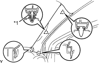
Text in Illustration *1 New Clip
-
Install a new clip.
-
Engage the 2 claws and 2 clips, and install the front pillar garnish.
-
-
INSTALL FRONT PILLAR GARNISH LH
Tech Tips
Use the same procedure as for the RH side.
-
INSTALL REAR DOOR OPENING TRIM WEATHERSTRIP RH
-
Install the rear door opening trim weatherstrip.
-
-
INSTALL REAR DOOR OPENING TRIM WEATHERSTRIP LH
Tech Tips
Use the same procedure as for the RH side.
-
INSTALL FRONT DOOR OPENING TRIM WEATHERSTRIP RH
-
Install the front door opening trim weatherstrip.
-
-
INSTALL FRONT DOOR OPENING TRIM WEATHERSTRIP LH
Tech Tips
Use the same procedure as for the RH side.
-
INSTALL COWL SIDE TRIM BOARD RH
-
Engage the 2 clips and stud bolt, and install the cowl side trim board.
-
-
INSTALL COWL SIDE TRIM BOARD LH
Tech Tips
Use the same procedure as for the RH side.
-
INSTALL REAR SEAT BACK ASSEMBLY (for Separate Seat Type)
-
Place the rear seat back in the cabin.
-
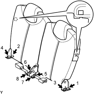
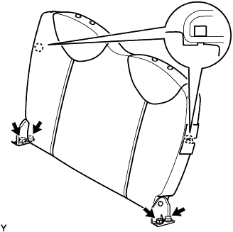
Using several steps, install and tighten the 4 nuts, 4 bolts and 2 rear seat inner belts uniformly in the sequence shown in the illustration.
- Torque:
- 22 N*m { 225 kgf*cm, 16 ft.*lbf, for 1, 2, 3 and 4 }
- 33.8 N*m { 345 kgf*cm, 25 ft.*lbf, for 5 and 6 }
- 42 N*m { 430 kgf*cm, 31 ft.*lbf, for 7 and 8 }
-
Lock the 2 hooks.
-
-
INSTALL REAR SEAT BACK ASSEMBLY (for Bench Seat Type)
-
Disengage the 2 hooks.
-
Remove the 2 nuts, 2 bolts and rear seat back.
-
-
INSTALL REAR SEAT CUSHION ASSEMBLY (for Separate Seat Type)
-
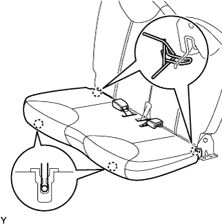
Engage the 4 hooks and install the rear seat cushion.
-
-
INSTALL REAR SEAT CUSHION ASSEMBLY (for Bench Seat Type)
-
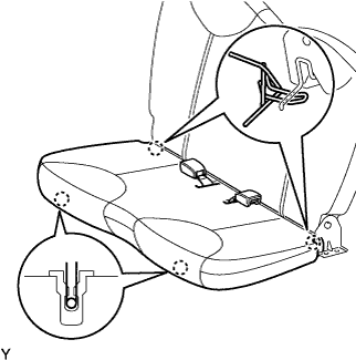
Engage the 4 hooks and install the rear seat cushion.
-
-
INSTALL FRONT SEAT ASSEMBLY LH
-
Place the front seat in the cabin.
-
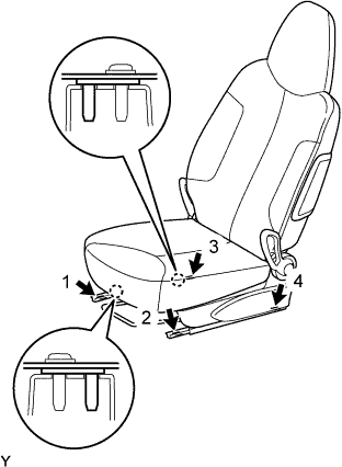
Using several steps, install and tighten the 4 bolts uniformly in the sequence shown in the illustration.
- Torque:
- 22 N*m { 225 kgf*cm, 16 ft.*lbf }
-
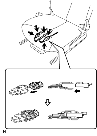
Connect the airbag connector, as shown in the illustration (w/ front seat side airbag).
-
Connect the buckle switch connector (driver seat only).
-
Install the wire harness clamp.
-
-
INSTALL FRONT SEAT ASSEMBLY RH
Tech Tips
Use the same procedure as for the LH side.
-
CONNECT CABLE TO NEGATIVE BATTERY TERMINAL
- Torque:
- 5.4 N*m { 55 kgf*cm, 48 in.*lbf }
-
INSPECT SRS WARNING LIGHT