FRONT PASSENGER AIRBAG ASSEMBLY INSTALLATION

CAUTION:
Some of these service operations affect the SRS airbag system. Be sure to read the precautionary notices concerning the SRS airbag system before servicing Click here.
-
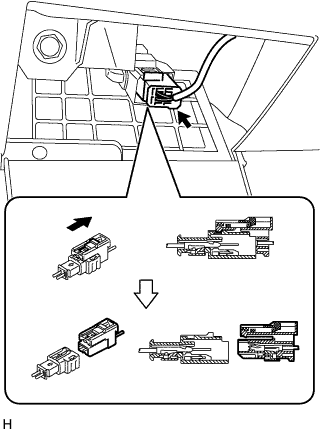
INSTALL INSTRUMENT PANEL WIRE NO. 3
Note
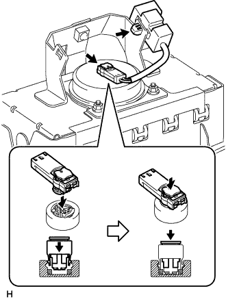
When handling the airbag connector, do not damage the airbag wire harness.
-
Connect the airbag connector, as shown in the illustration.
-
Install the connector clamp.
-
-
INSTALL FRONT PASSENGER AIRBAG ASSEMBLY
-
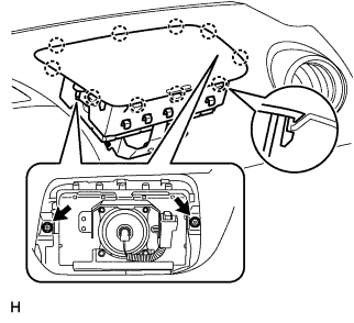
Engage the 10 claws and install the front passenger airbag.
-
Tighten the 2 nuts.
- Torque:
- 6.0 N*m { 60 kgf*cm, 53 in.*lbf }
-
-
INSTALL INSTRUMENT PANEL ASSEMBLY
-
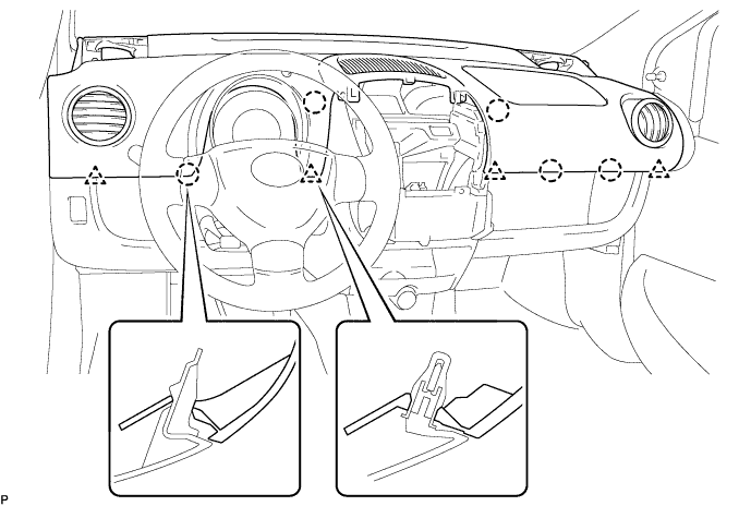
Engage the 4 clips and 5 claws and install the instrument panel assembly.
Note
Make sure that there are no gaps between the instrument panel upper and instrument panel lower panel.
-
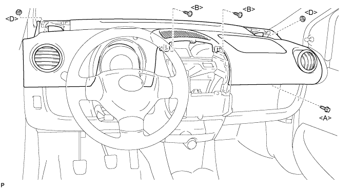
Install the bolt <A>, 2 nuts <D> and 2 screws <B>.
- Torque:
- 18 N*m { 184 kgf*cm, 13 ft.*lbf, for bolt <A> }
- 6.0 N*m { 61 kgf*cm, 53 in.*lbf, for nut <D> }
-
Connect the airbag connector, as shown in the illustration.
-
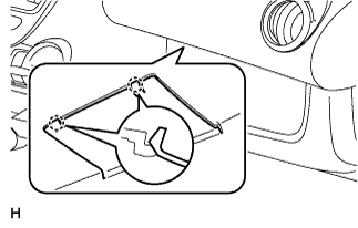
Engage the 2 claws and close the cover.
-
-
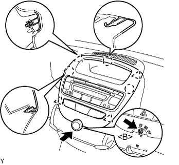
INSTALL INSTRUMENT CLUSTER FINISH PANEL SUB-ASSEMBLY CENTER
-
Connect the connectors.
-
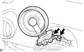
Engage the 4 clips and 3 claws and install the instrument cluster finish panel center.
-
Install the screw <B>.
-
Install the control knob.
-
-
INSTALL TACHOMETER ASSEMBLY (w/ Tachometer)
-
Install the tachometer with the bolt.
- Torque:
- 6.5 N*m { 66 kgf*cm, 58 in.*lbf }
-
Connect the connector.
-
-
INSTALL STEERING COLUMN COVER UPPER
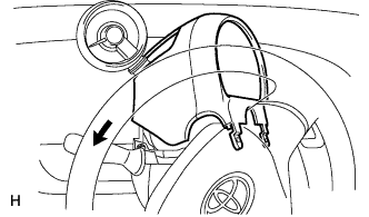
-
Install the steering column cover upper, as shown in the illustration (w/ tachometer).
-
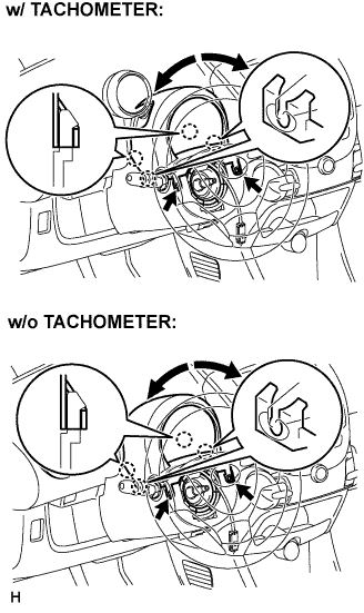
While turning the steering wheel to the right and left, engage the 4 claws and install the steering column cover upper with the 2 screws.
- Torque:
- 2.0 N*m { 20 kgf*cm, 18 in.*lbf }
-
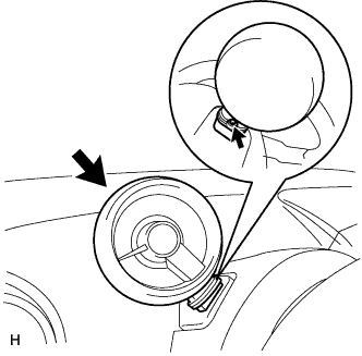
Tighten the screw behind the tachometer (w/ tachometer).
Note
Tighten the screw if the tachometer has been extended and the column cover has been removed.
- Torque:
- 9.0 N*m { 92 kgf*cm, 80 in.*lbf }
-
-
INSTALL FRONT NO. 1 SPEAKER
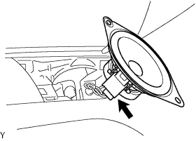
-
Connect the connector.
-
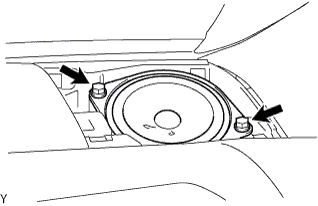
Install the 2 screws.
-
-
INSTALL INSTRUMENT PANEL SPEAKER PANEL SUB-ASSEMBLY NO. 2
-
Engage the 2 claws.
-
-
INSTALL INSTRUMENT PANEL SPEAKER PANEL SUB-ASSEMBLY NO. 1
Tech Tips
Use the same procedure as for the RH side.
-
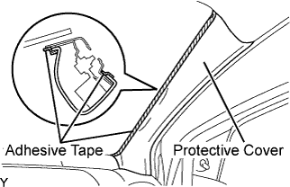
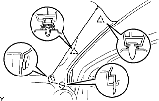
INSTALL FRONT PILLAR GARNISH RH (w/ Curtain Shield Airbag)
-
Remove the adhesive tape and protective cover.
-
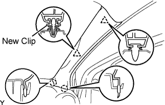
Install a new clip.
-
Engage the 2 claws and 2 clips, and install the front pillar garnish.
-
-
INSTALL FRONT PILLAR GARNISH LH (w/ Curtain Shield Airbag)
Tech Tips
Use the same procedure as for the RH side.
-
INSTALL FRONT PILLAR GARNISH RH (w/o Curtain Shield Airbag)
-
Engage the 2 claws and 2 clips, and install the front pillar garnish.
-
-
INSTALL FRONT PILLAR GARNISH LH (w/o Curtain Shield Airbag)
Tech Tips
Use the same procedure as for the RH side.
-
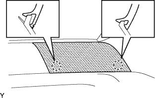
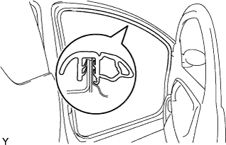
INSTALL FRONT DOOR OPENING TRIM WEATHERSTRIP RH
-
Remove the front door opening trim weatherstrip.
-
-
INSTALL FRONT DOOR OPENING TRIM WEATHERSTRIP LH
Tech Tips
Use the same procedure as for the RH side.
-
CONNECT CABLE TO NEGATIVE BATTERY TERMINAL
- Torque:
- 5.4 N*m { 55 kgf*cm, 48 in.*lbf }
-
INSPECT SRS WARNING LIGHT