AIRBAG SYSTEM, Diagnostic DTC:B1651

| DTC Code | DTC Name |
|---|---|
| B1651 | Airbag ON-OFF Switch |
DESCRIPTION
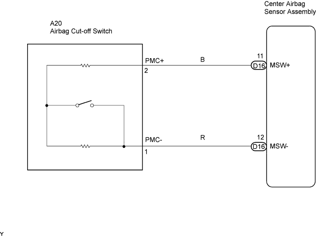
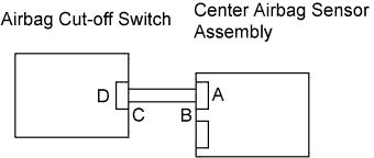
The passenger airbag cut-off switch circuit consists of the center airbag sensor assembly and the airbag cut off switch.
DTC B1651 is set when a malfunction is detected in the airbag cut-off switch circuit.
| DTC No. | DTC Detecting Conditions | Trouble Areas |
|---|---|---|
| B1651 |
|
|
WIRING DIAGRAM
INSPECTION PROCEDURE
CAUTION:
In order to prevent unexpected airbag deployment, disconnect the following connectors before inspecting parts such as wire harnesses, if the application of tester probes to the center airbag sensor assembly connector is necessary.
-
Turn the ignition switch to the LOCK position.
-
Disconnect the negative (-) terminal cable from the battery, and wait for at least 90 seconds.
-
Disconnect the connectors from the center airbag sensor assembly.
-
Disconnect the connectors from the steering pad.
-
Disconnect the connector from the front passenger airbag assembly.
-
Disconnect the connector from the front seat outer belt assembly LH.
-
Disconnect the connector from the front seat outer belt assembly RH.
Tech Tips
Skip the following steps if side and curtain shield airbags are not fitted.
-
Disconnect the connector from the front seat airbag assembly LH.
-
Disconnect the connector from the front seat airbag assembly RH.
-
Disconnect the connector from the curtain shield airbag assembly LH.
-
Disconnect the connector from the curtain shield airbag assembly RH.
PROCEDURE
-
CHECK DTC
-
Turn the ignition switch to the ON position.
-
Clear any DTCs stored in the memory.
-
Turn the ignition switch to the LOCK position.
-
Turn the ignition switch to the ON position and wait for at least 60 seconds.
-
Check for DTCs.
OK DTC B1651 is not output. Tech Tips
DTCs other than B1651 may be output at this time, but they are not related to this check.
NG 
CHECK CONNECTION OF CONNECTOR Click here
OK 
USE SIMULATION METHOD TO CHECK
-
-
CHECK CONNECTION OF CONNECTOR
-
Turn the ignition switch to the LOCK position.
-
Disconnect the negative (-) terminal cable from the battery, and wait for at least 90 seconds.
-
Check that the connectors are properly connected to the center airbag sensor assembly and the airbag cut-off switch.
OK The connectors are properly connected.
NG 
CONNECT CONNECTOR
OK 
-
-
CHECK CONNECTOR
-
Check that the connectors (on the center airbag sensor assembly side and airbag cut-off switch side) are not damaged Click here.
OK The connectors are not deformed or damaged.
NG
REPAIR OR REPLACE WIRE HARNESS AND CONNECTORS
OK
-
-
INSPECT AIRBAG CUT-OFF SWITCH
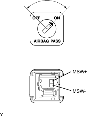
-
Disconnect the C29 airbag cut-off switch connector.
-
Measure the resistance.
Standard Resistance Switch Condition Tester Connection Specified Condition OFF 6 (MSW+) -
3 (MSW-)
90 to 110 Ω ON 6 (MSW+) -
3 (MSW-)
360 to 440 Ω
NG
REPLACE AIRBAG CUT-OFF SWITCH
OK
-
-
CHECK INSTRUMENT PANEL WIRE (FOR OPEN)
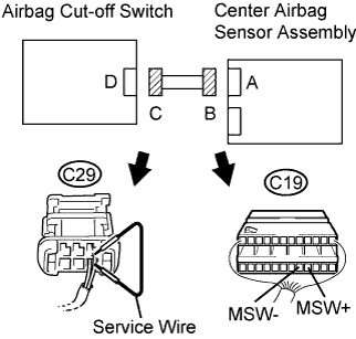
-
Disconnect the instrument panel wire connector from the airbag cut-off switch.
-
Using a service wire, connect C29-6 (MSW+) and C29-3 (MSW-) of connector C.
Note
Do not forcibly insert the service wire into the terminals of the connector when connecting.
-
Measure the resistance.
Standard Resistance Tester Connection Condition Specified Condition C19-9 (MSW+) -
C19-8 (MSW-)
Always Below 1 Ω
NG
REPAIR OR REPLACE INSTRUMENT PANEL WIRE
OK
-
-
CHECK INSTRUMENT PANEL WIRE (FOR SHORT)
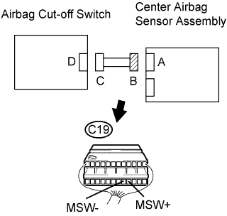
-
Disconnect the service wire from connector C.
-
Measure the resistance.
Standard Resistance Tester Connection Condition Specified Condition C19-9 (MSW+) -
C19-8 (MSW-)
Always 1 MΩ or Higher
NG
REPAIR OR REPLACE INSTRUMENT PANEL WIRE
OK
-
-
CHECK INSTRUMENT PANEL WIRE (TO B+)
-
Connect the negative (-) terminal cable to the battery, and wait for at least 2 seconds.
-
Turn the ignition switch to the ON position.
-
Measure the voltage.
Standard Voltage Tester Connection Condition Specified Condition C19-9 (MSW+) -
Body ground
Ignition switch ON Below 1 V C19-8 (MSW-) -
Body ground
Ignition switch ON Below 1 V
NG
REPAIR OR REPLACE INSTRUMENT PANEL WIRE
OK
-
-
CHECK INSTRUMENT PANEL WIRE (TO GROUND)
-
Turn the ignition switch to the LOCK position.
-
Disconnect the negative (-) terminal cable from the battery, and wait for at least 90 seconds.
-
Measure the resistance.
Standard Resistance Tester Connection Condition Specified Condition C19-9 (MSW+) -
Body ground
Always 1 MΩ or Higher C19-8 (MSW-) -
Body ground
Always 1 MΩ or Higher
NG
REPAIR OR REPLACE INSTRUMENT PANEL WIRE
OK
-
-
CHECK CENTER AIRBAG SENSOR ASSEMBLY
-
Connect the connectors to the center airbag sensor assembly and airbag cut-off switch.
-
Connect the negative (-) terminal cable to the battery, and wait for at least 2 seconds.
-
Turn the ignition switch to the ON position, and wait for at least 60 seconds.
-
Clear any DTCs stored in the memory.
-
Turn the ignition switch to the LOCK position.
-
Turn the ignition switch to the ON position, and wait for at least 60 seconds.
-
Check for DTCs.
OK DTC B1651 is not output. Tech Tips
DTCs other than B1651 may be output at this time, but they are not related to this check.
NG
REPLACE CENTER AIRBAG SENSOR ASSEMBLY
OK
USE SIMULATION METHOD TO CHECK
-