AIRBAG SYSTEM, Diagnostic DTC:B1620, B1625

| DTC Code | DTC Name |
|---|---|
| B1620 | Side Airbag Sensor RH Circuit Malfunction |
| B1625 | Front Passenger Side - Side Airbag Sensor |
DESCRIPTION
The configuration of the side airbag sensor LH is the same as that of the RH.
When the center airbag sensor assembly receives signals from the frontal deceleration sensor, it determines whether or not the SRS should be activated.
DTC B1620 is set when a malfunction is detected in the driver's side side airbag sensor circuit.
DTC B1625 is set when a malfunction is detected in the passenger's side side airbag sensor circuit.
| DTC No. | DTC Detecting Conditions | Trouble Areas |
|---|---|---|
| B1620 |
|
|
| B1625 |
|
|
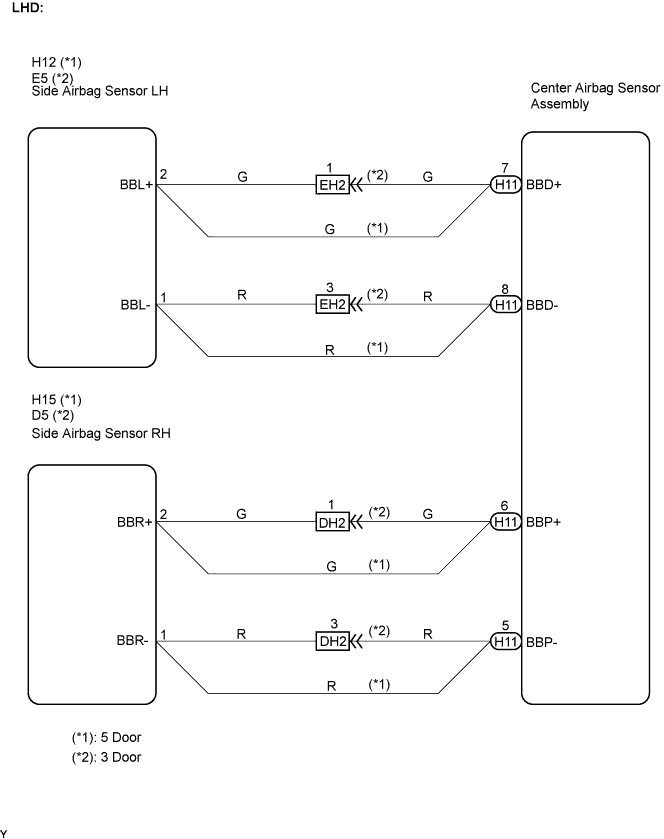
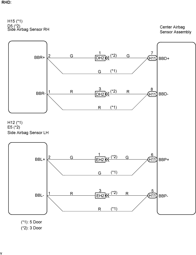
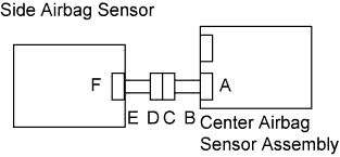
WIRING DIAGRAM
INSPECTION PROCEDURE
Note
In order to prevent unexpected airbag deployment, disconnect the following connectors before inspecting parts such as wire harnesses, if the application of tester probes to the center airbag sensor assembly connector is necessary.
-
Turn the ignition switch to the LOCK position.
-
Disconnect the negative (-) terminal cable from the battery, and wait for at least 90 seconds.
-
Disconnect the connectors from the center airbag sensor assembly.
-
Disconnect the connectors from the steering pad.
-
Disconnect the connector from the front passenger airbag assembly.
-
Disconnect the connector from the front seat outer belt assembly LH.
-
Disconnect the connector from the front seat outer belt assembly RH.
Tech Tips
Skip the following steps if side and curtain shield airbags are not fitted.
-
Disconnect the connector from the front seat airbag assembly LH.
-
Disconnect the connector from the front seat airbag assembly RH.
-
Disconnect the connector from the curtain shield airbag assembly LH.
-
Disconnect the connector from the curtain shield airbag assembly RH.
PROCEDURE
-
CHECK DTC
-
Proceed to the appropriate step according to DTC readings.
-
Check the DTC Click here.
Result DTC B1620 output. A DTC B1625 output. B DTC B1620 and B1625 output. C
-
B 
CHECK CONNECTION OF CONNECTOR Click here
C
CHECK CONNECTION OF CONNECTOR Click here
A 
-
-
CHECK CONNECTION OF CONNECTOR
-
Turn the ignition switch to the LOCK position.
-
Disconnect the negative (-) terminal cable from the battery, and wait for at least 90 seconds.
-
Check that the connectors are properly connected to the center airbag sensor assembly and the driver's side side airbag sensor.
OK The connectors are properly connected.
NG 
CONNECT CONNECTOR
OK
-
-
CHECK CONNECTOR
-
Check that the connectors (on the center airbag sensor assembly side and driver's side side airbag sensor) are not damaged Click here.
Result OK (3 Door) A OK (5 Door) B NG C
B
CHECK SIDE AIRBAG SENSOR D SEAT SIDE CIRCUIT (FOR OPEN) Click here
C
REPAIR OR REPLACE WIRE HARNESS
A
-
-
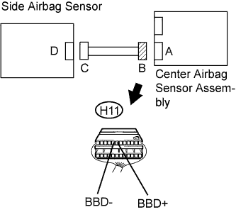
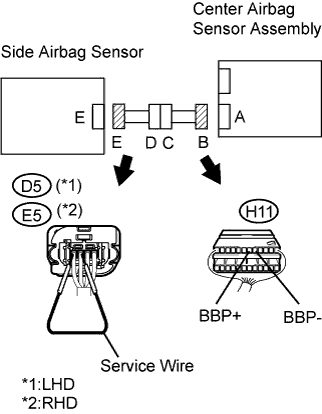
CHECK SIDE AIRBAG SENSOR D SEAT SIDE CIRCUIT (FOR OPEN)
-
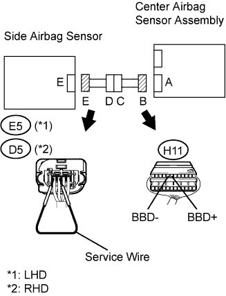
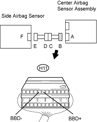
Disconnect the connectors from the center airbag sensor assembly and the driver's side side airbag sensor.
-
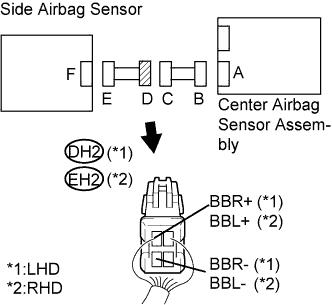
LHD:
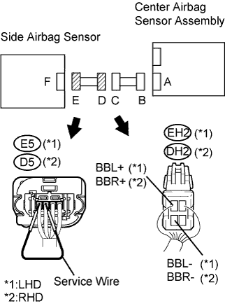
Using a service wire, connect E5-2 (BBL+) and E5-1 (BBL-) of connector E.
Note
Do not forcibly insert the service wire into the terminals of the connector when connecting.
-
RHD:
Using a service wire, connect D5-2 (BBR+) and D5-1 (BBR-) of connector E.
Note
Do not forcibly insert the service wire into the terminals of the connector when connecting.
-
Measure the resistance.
Standard Resistance Tester Connection Condition Specified Condition H11-7 (BBD+) - H11-8 (BBD-) Always Below 1 Ω
NG
CHECK FRONT DOOR WIRE D SEAT SIDE (FOR OPEN) Click here
OK
-
-
CHECK SIDE AIRBAG SENSOR D SEAT SIDE CIRCUIT (FOR SHORT)
-
Disconnect the service wire from connector E.
-
Measure the resistance.
Standard Resistance Tester Connection Condition Specified Condition H11-7 (BBD+) - H11-8 (BBD-) Always 1 MΩ or Higher
NG
CHECK FRONT DOOR WIRE D SEAT SIDE (FOR SHORT) Click here
OK
-
-
CHECK SIDE AIRBAG SENSOR D SEAT SIDE CIRCUIT (TO B+)
-
Connect the negative (-) terminal cable to the battery, and wait for at least 2 seconds.
-
Turn the ignition switch to the ON position.
-
Measure the voltage.
Standard Voltage Tester Connection Condition Specified Condition H11-7 (BBD+) - Body ground Ignition switch ON Below 1 V H11-8 (BBD-) - Body ground Ignition switch ON Below 1 V
NG
CHECK FRONT DOOR WIRE D SEAT SIDE (TO B+) Click here
OK
-
-
CHECK SIDE AIRBAG SENSOR D SEAT SIDE CIRCUIT (TO GROUND)
-
Turn the ignition switch to the LOCK position.
-
Disconnect the negative (-) terminal cable from the battery, and wait for at least 90 seconds.
-
Measure the resistance.
Standard Resistance Tester Connection Condition Specified Condition H11-7 (BBD+) - Body ground Always 1 MΩ or Higher H11-8 (BBD-) - Body ground Always 1 MΩ or Higher
NG
CHECK FRONT DOOR WIRE D SEAT SIDE (TO GROUND) Click here
OK
-
-
CHECK SIDE AIRBAG SENSOR
-
Connect the connectors to the center airbag sensor assembly.
-
Interchange the driver's side side airbag sensor with the passenger's side side airbag sensor and connect the connectors to them.
-
Connect the negative (-) terminal cable to the battery, and wait for at least 2 seconds.
-
Turn the ignition switch to the ON position, and wait for at least 60 seconds.
-
Clear any DTCs stored in the memory Click here.
-
Turn the ignition switch to the LOCK position.
-
Turn the ignition switch to the ON position, and wait for at least 60 seconds.
-
Check for DTCs Click here.
Result DTC B1620 output. A DTC B1625 output (LHD). B DTC B1625 output (RHD). C Neither DTC B1620 nor B1625 output. D
A
REPLACE CENTER AIRBAG SENSOR ASSEMBLY
B
REPLACE SIDE AIRBAG SENSOR LH (LHD)
C
REPLACE SIDE AIRBAG SENSOR RH (RHD)
D 
USE SIMULATION METHOD TO CHECK
-
-
CHECK FRONT DOOR WIRE D SEAT SIDE (FOR OPEN)
-
Disconnect the front door wire connector from the instrument panel wire.
Tech Tips
The service wire has already been inserted into connector E.
-
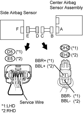
Measure the resistance.
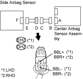
Standard Resistance Tester Connection Condition Specified Condition EH2-1 (BBL+) - EH2-3 (BBL-) (*1) Always Below 1 Ω DH2-1 (BBR+) - DH2-3 (BBR-) (*2) Always Below 1 Ω *1: LHD
*2: RHD
NG
REPAIR OR REPLACE FRONT DOOR WIRE LH (LHD)
NG
REPAIR OR REPLACE FRONT DOOR WIRE RH (RHD)
OK
REPAIR OR REPLACE FLOOR WIRE
-
-
CHECK FRONT DOOR WIRE D SEAT SIDE (FOR SHORT)
-
Disconnect the front door wire connector from the instrument panel wire.
-
Measure the resistance.
Standard Resistance Tester Connection Condition Specified Condition EH2-1 (BBL+) - EH2-3 (BBL-) (*1) Always 1 MΩ or Higher DH2-1 (BBR+) - DH2-3 (BBL-) (*2) Always 1 MΩ or Higher *1: LHD
*2: RHD
NG
REPAIR OR REPLACE FRONT DOOR WIRE LH (LHD)
NG
REPAIR OR REPLACE FRONT DOOR WIRE RH (RHD)
OK
REPAIR OR REPLACE FLOOR WIRE
-
-
CHECK FRONT DOOR WIRE D SEAT SIDE (TO B+)
-
Turn the ignition switch to the LOCK position.
-
Disconnect the negative (-) terminal cable from the battery, and wait for at least 90 seconds.
-
Disconnect the front door wire connector from the instrument panel wire.
-
Connect the negative (-) terminal cable to the battery, and wait for at least 2 seconds.
-
Turn the ignition switch to the ON position.
-
Measure the voltage.
Standard Voltage Tester Connection Condition Specified Condition EH2-1 (BBL+) - Body ground (*1) Ignition switch ON Below 1 V EH2-3 (BBL-) - Body ground (*1) Ignition switch ON Below 1 V DH2-1 (BBR+) - Body ground (*2) Ignition switch ON Below 1 V DH2-3 (BBR-) - Body ground (*2) Ignition switch ON Below 1 V *1: LHD
*2: RHD
NG
REPAIR OR REPLACE FRONT DOOR WIRE LH (LHD)
NG
REPAIR OR REPLACE FRONT DOOR WIRE RH (RHD)
OK
REPAIR OR REPLACE FLOOR WIRE
-
-
CHECK FRONT DOOR WIRE D SEAT SIDE (TO GROUND)
-
Disconnect the front door wire connector from the instrument panel wire.
-
Measure the resistance.
Standard Resistance Tester Connection Condition Specified Condition EH2-1 (BBL+) - Body ground Always 1 MΩ or Higher EH2-3 (BBL-) - Body ground Always 1 MΩ or Higher DH2-1 (BBR+) - Body ground (*2) Always 1 MΩ or Higher DH2-3 (BBR-) - Body ground (*2) Always 1 MΩ or Higher *1: LHD
*2: RHD
NG
REPAIR OR REPLACE FRONT DOOR WIRE LH (LHD)
NG
REPAIR OR REPLACE FRONT DOOR WIRE RH (RHD)
OK
REPAIR OR REPLACE FLOOR WIRE
-
-
CHECK SIDE AIRBAG SENSOR D SEAT SIDE CIRCUIT (FOR OPEN)
-
Disconnect the connectors from the center airbag sensor assembly and the driver's side side airbag sensor.
-
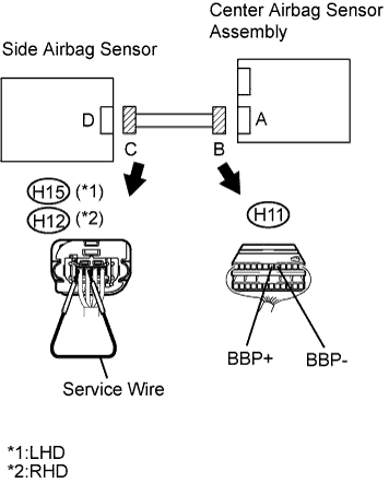
LHD:
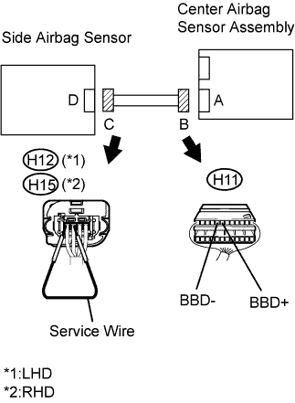
Using a service wire, connect H12-2 (BBL+) and H12-1 (BBL-) of connector C.
Note
Do not forcibly insert the service wire into the terminals of the connector when connecting.
-
RHD:
Using a service wire, connect H15-2 (BBR+) and H15-1 (BBR-) of connector C.
Note
Do not forcibly insert the service wire into the terminals of the connector when connecting.
-
Measure the resistance.
Standard Resistance Tester Connection Condition Specified Condition H11-7 (BBD+) - H11-8 (BBD-) Always Below 1 Ω
NG
REPAIR OR REPLACE FLOOR WIRE
OK
-
-
CHECK SIDE AIRBAG SENSOR D SEAT SIDE CIRCUIT (FOR SHORT)
-
Disconnect the service wire from connector C.
-
Measure the resistance.
Standard Resistance Tester Connection Condition Specified Condition H11-7 (BBD+) - H11-8 (BBD-) Always 1 MΩ or Higher
NG
REPAIR OR REPLACE FLOOR WIRE
OK
-
-
CHECK SIDE AIRBAG SENSOR D SEAT SIDE CIRCUIT (TO B+)
-
Connect the negative (-) terminal cable to the battery, and wait for at least 2 seconds.
-
Turn the ignition switch to the ON position.
-
Measure the voltage.
Standard Voltage Tester Connection Condition Specified Condition H11-7 (BBD+) - Body ground Ignition switch ON Below 1 V H11-8 (BBD-) - Body ground Ignition switch ON Below 1 V
NG
REPAIR OR REPLACE FLOOR WIRE
OK
-
-
CHECK SIDE AIRBAG SENSOR D SEAT SIDE CIRCUIT (TO GROUND)
-
Turn the ignition switch to the LOCK position.
-
Disconnect the negative (-) terminal cable from the battery, and wait for at least 90 seconds.
-
Measure the resistance.
Standard Resistance Tester Connection Condition Specified Condition H11-7 (BBD+) - Body ground Always 1 MΩ or Higher H11-8 (BBD-) - Body ground Always 1 MΩ or Higher
OK
CHECK SIDE AIRBAG SENSOR Click here
NG
REPAIR OR REPLACE FLOOR WIRE
-
-
CHECK CONNECTION OF CONNECTOR
-
Turn the ignition switch to the LOCK position.
-
Disconnect the negative (-) terminal cable from the battery, and wait for at least 90 seconds.
-
Check that the connectors are properly connected to the center airbag sensor assembly and the passenger's side side airbag sensor front LH.
OK The connectors are properly connected.
NG
CONNECT CONNECTOR
OK
-
-
CHECK CONNECTOR
-
Check that the connectors (on the center airbag sensor assembly and passenger's side side airbag sensor) are not damaged Click here.
Result OK (3 Door) A OK (5 Door) B NG C
B
CHECK SIDE AIRBAG SENSOR P SEAT SIDE CIRCUIT (FOR OPEN) Click here
C
REPAIR OR REPLACE WIRE HARNESS
A
-
-
CHECK SIDE AIRBAG SENSOR P SEAT SIDE CIRCUIT (FOR OPEN)
-
Disconnect the connectors from the center airbag sensor assembly and the passenger's side side airbag sensor.
-
LHD:
Using a service wire, connect D5-2 (BBR+) and D5-1 (BBR-) of connector E.
Note
Do not forcibly insert the service wire into the terminals of the connector when connecting.
-
RHD:
Using a service wire, connect E5-2 (BBL+) and E5-1 (BBL-) of connector E.
Note
Do not forcibly insert the service wire into the terminals of the connector when connecting.
-
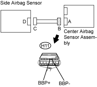
Measure the resistance.
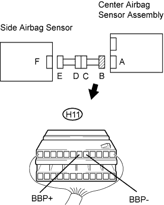
Standard Resistance Tester Connection Condition Specified Condition H11-6 (BBP+) - H11-5 (BBP-) Always Below 1 Ω
NG
CHECK FRONT DOOR WIRE P SEAT SIDE (FOR OPEN) Click here
OK
-
-
CHECK SIDE AIRBAG SENSOR P SEAT SIDE CIRCUIT (FOR SHORT)
-
Disconnect the service wire from connector E.
-
Measure the resistance.
Standard Resistance Tester Connection Condition Specified Condition H11-6 (BBP+) - H11-5 (BBP-) Always 1 MΩ or Higher
NG
CHECK FRONT DOOR WIRE P SEAT SIDE (FOR SHORT) Click here
OK
-
-
CHECK SIDE AIRBAG SENSOR P SEAT SIDE CIRCUIT (TO B+)
-
Connect the negative (-) terminal cable to the battery, and wait for at least 2 seconds.
-
Turn the ignition switch to the ON position.
-
Measure the voltage.
Standard Voltage Tester Connection Condition Specified Condition H11-6 (BBP+) - Body ground Ignition switch ON Below 1 V H11-5 (BBP-) - Body ground Ignition switch ON Below 1 V
NG
CHECK FRONT DOOR WIRE P SEAT SIDE (TO B+) Click here
OK
-
-
CHECK SIDE AIRBAG SENSOR P SEAT SIDE CIRCUIT (TO GROUND)
-
Turn the ignition switch to the LOCK position.
-
Disconnect the negative (-) terminal cable from the battery, and wait for at least 90 seconds.
-
Measure the resistance.
Standard Resistance Tester Connection Condition Specified Condition H11-6 (BBP+) - Body ground Always 1 MΩ or Higher H11-5 (BBP-) - Body ground Always 1 MΩ or Higher
NG
CHECK FRONT DOOR WIRE P SEAT SIDE (TO GROUND) Click here
OK
-
-
CHECK SIDE AIRBAG SENSOR
-
Connect the connectors to the center airbag sensor assembly.
-
Interchange the driver's side airbag sensor with the passenger's side side airbag sensor and connect the connectors to them.
-
Connect the negative (-) terminal cable to the battery, and wait for at least 2 seconds.
-
Turn the ignition switch to the ON position, and wait for at least 60 seconds.
-
Clear any DTCs stored in the memory Click here.
-
Turn the ignition switch to the LOCK position.
-
Turn the ignition switch to the ON position, and wait for at least 60 seconds.
-
Check for DTCs Click here.
Result DTC B1625 output A DTC B1620 output (LHD) B DTC B1620 output (RHD) C Neither DTC B1620 nor B1625 output D
A
REPLACE CENTER AIRBAG SENSOR ASSEMBLY
B
REPLACE SIDE AIRBAG SENSOR RH (LHD)
C
REPLACE SIDE AIRBAG SENSOR LH (RHD)
D
USE SIMULATION METHOD TO CHECK
-
-
CHECK FRONT DOOR WIRE P SEAT SIDE (FOR OPEN)
-
Disconnect the front door wire connector from the instrument panel wire.
Tech Tips
The service wire has already been inserted into connector E.
-
Measure the resistance.
Standard Resistance Tester Connection Condition Specified Condition DH2-1 (BBR+) - DH2-3 (BBR-) (*1) Always Below 1 Ω EH2-1 (BBL+) - EH2-3 (BBL-) (*2) Always Below 1 Ω *1: LHD
*2: RHD
NG
REPAIR OR REPLACE FRONT DOOR WIRE RH (LHD)
NG
REPAIR OR REPLACE FRONT DOOR WIRE LH (RHD)
OK
REPAIR OR REPLACE FLOOR WIRE
-
-
CHECK FRONT DOOR WIRE P SEAT SIDE (FOR SHORT)
-
Disconnect the front door wire connector from the instrument panel wire.
-
Measure the resistance.
Standard Resistance Tester Connection Condition Specified Condition DH2-1 (BBR+) - DH2-3 (BBR-) (*1) Always 1 MΩ or Higher EH2-1 (BBL+) - EH2-3 (BBL-) (*2) Always 1 MΩ or Higher *1: LHD
*2: RHD
NG
REPAIR OR REPLACE FRONT DOOR WIRE RH (LHD)
NG
REPAIR OR REPLACE FRONT DOOR WIRE LH (RHD)
OK
REPAIR OR REPLACE FLOOR WIRE
-
-
CHECK FRONT DOOR WIRE P SEAT SIDE (TO B+)
-
Turn the ignition switch to the LOCK position.
-
Disconnect the negative (-) terminal cable from the battery, and wait for at least 90 seconds.
-
Disconnect the front door wire connector from the instrument panel wire.
-
Connect the negative (-) terminal cable to the battery, and wait for at least 2 seconds.
-
Turn the ignition switch to the ON position.
-
Measure the voltage.
Standard Voltage Tester Connection Condition Specified Condition DH2-1 (BBR+) - Body ground (*1) Ignition switch ON Below 1 V DH2-3 (BBR-) - Body ground (*1) Ignition switch ON Below 1 V EH2-1 (BBL+) - Body ground (*2) Ignition switch ON Below 1 V EH2-3 (BBL-) - Body ground (*2) Ignition switch ON Below 1 V *1: LHD
*2: RHD
NG
REPAIR OR REPLACE FRONT DOOR WIRE RH (LHD)
NG
REPAIR OR REPLACE FRONT DOOR WIRE LH (RHD)
OK
REPAIR OR REPLACE FLOOR WIRE
-
-
CHECK FRONT DOOR WIRE P SEAT SIDE (TO GROUND)
-
Disconnect the front door wire connector from the instrument panel wire.
-
Measure the resistance.
Standard Resistance Tester Connection Condition Specified Condition DH2-1 (BBR+) - Body ground (*1) Always 1 MΩ or Higher DH2-3 (BBR-) - Body ground (*1) Always 1 MΩ or Higher EH2-1 (BBL+) - Body ground (*2) Always 1 MΩ or Higher EH2-3 (BBL-) - Body ground (*2) Always 1 MΩ or Higher *1: LHD
*2: RHD
NG
REPAIR OR REPLACE FRONT DOOR WIRE RH (LHD)
NG
REPAIR OR REPLACE FRONT DOOR WIRE LH (RHD)
OK
REPAIR OR REPLACE FLOOR WIRE
-
-
CHECK SIDE AIRBAG SENSOR P SEAT SIDE CIRCUIT (FOR OPEN)
-
Disconnect the connectors from the center airbag sensor assembly and the passenger's side side airbag sensor.
-
LHD:
Using a service wire, connect H15-2 (BBR+) and H15-1 (BBR-) of connector C.
Note
Do not forcibly insert the service wire into the terminals of the connector when connecting.
-
RHD:
Using a service wire, connect H12-2 (BBL+) and H12-1 (BBL-) of connector C.
Note
Do not forcibly insert the service wire into the terminals of the connector when connecting.
-
Measure the resistance.
Standard Resistance Tester Connection Condition Specified Condition H11-6 (BBP+) - H11-5 (BBP-) Always Below 1 Ω
NG
REPAIR OR REPLACE FLOOR WIRE
OK
-
-
CHECK SIDE AIRBAG SENSOR P SEAT SIDE CIRCUIT (FOR SHORT)
-
Disconnect the service wire from connector C.
-
Measure the resistance.
Standard Resistance Tester Connection Condition Specified Condition H11-6 (BBP+) - H11-5 (BBP-) Always 1 MΩ or Higher
NG
REPAIR OR REPLACE FLOOR WIRE
OK
-
-
CHECK SIDE AIRBAG SENSOR P SEAT SIDE CIRCUIT (TO B+)
-
Connect the negative (-) terminal cable to the battery, and wait for at least 2 seconds.
-
Turn the ignition switch to the ON position.
-
Measure the voltage.
Standard Voltage Tester Connection Condition Specified Condition H11-6 (BBP+) - Body ground Ignition switch ON Below 1 V H11-5 (BBP-) - Body ground Ignition switch ON Below 1 V
NG
REPAIR OR REPLACE FLOOR WIRE
OK
-
-
CHECK SIDE AIRBAG SENSOR P SEAT SIDE CIRCUIT (TO GROUND)
-
Turn the ignition switch to the LOCK position.
-
Disconnect the negative (-) terminal cable from the battery, and wait for at least 90 seconds.
-
Measure the resistance.
Standard Resistance Tester Connection Condition Specified Condition H11-6 (BBP+) - Body ground Always 1 MΩ or Higher H11-5 (BBP-) - Body ground Always 1 MΩ or Higher
OK
CHECK SIDE AIRBAG SENSOR Click here
NG
REPAIR OR REPLACE FLOOR WIRE
-
-
CHECK CONNECTION OF CONNECTOR
-
Turn the ignition switch to the LOCK position.
-
Disconnect the negative (-) terminal cable from the battery, and wait for at least 90 seconds.
-
Check that the connectors are properly connected to the center airbag sensor assembly, the driver's side side airbag sensor and the passenger's side side airbag sensor.
OK The connectors are properly connected.
NG
CONNECT CONNECTOR
OK
-
-
CHECK CONNECTOR
-
Check that the connectors (on the center airbag sensor assembly, driver's side side airbag sensor and passenger's side side airbag sensor) are not damaged Click here.
OK The connectors are not deformed or damaged. Result OK (3 Door) A OK (5 Door) B NG C
B
CHECK SIDE AIRBAG SENSOR D SEAT SIDE CIRCUIT (FOR OPEN) Click here
C
REPAIR OR REPLACE WIRE HARNESS
A
-
-
CHECK SIDE AIRBAG SENSOR D SEAT SIDE CIRCUIT (FOR OPEN)
-
Disconnect the connectors from the center airbag sensor assembly and the side airbag sensor.
-
Using a service wire, connect E5-2 (BBD+) and E5-1 (BBD-) of connector E.
Note
Do not forcibly insert the service wire into the terminals of the connector when connecting.
-
RHD:
Using a service wire, connect D5-2 (BBR+) and D5-1 (BBR-) of connector E.
Note
Do not forcibly insert the service wire into the terminals of the connector when connecting.
-
Measure the resistance.
Standard Resistance Tester Connection Condition Specified Condition H11-7 (BBD+) - H11-8 (BBD-) Always Below 1 Ω
NG
CHECK FRONT DOOR WIRE D SEAT SIDE (FOR OPEN) Click here
OK
-
-
CHECK SIDE AIRBAG SENSOR D SEAT SIDE CIRCUIT (FOR SHORT)
-
Disconnect the service wire from connector E.
-
Measure the resistance.
Standard Resistance Tester Connection Condition Specified Condition H11-7 (BBD+) - H11-8 (BBD-) Always 1 MΩ or Higher
NG
CHECK FRONT DOOR WIRE D SEAT SIDE (FOR SHORT) Click here
OK
-
-
CHECK SIDE AIRBAG SENSOR D SEAT SIDE CIRCUIT (TO B+)
-
Connect the negative (-) terminal cable to the battery, and wait for at least 2 seconds.
-
Turn the ignition switch to the ON position.
-
Measure the voltage.
Standard Voltage Tester Connection Condition Specified Condition H11-7 (BBD+) - Body ground Ignition switch ON Below 1 V H11-8 (BBD-) - Body ground Ignition switch ON Below 1 V
NG
CHECK FRONT DOOR WIRE D SEAT SIDE (TO B+) Click here
OK
-
-
CHECK SIDE AIRBAG SENSOR D SEAT SIDE CIRCUIT (TO GROUND)
-
Turn the ignition switch to the LOCK position.
-
Disconnect the negative (-) terminal cable from the battery, and wait for at least 90 seconds.
-
Measure the resistance.
Standard Resistance Tester Connection Condition Specified Condition H11-7 (BBD+) - Body ground Always 1 MΩ or Higher H11-8 (BBD-) - Body ground Always 1 MΩ or Higher
OK
CHECK SIDE AIRBAG SENSOR P SEAT SIDE CIRCUIT (FOR OPEN) Click here
NG
CHECK FRONT DOOR WIRE D SEAT SIDE (TO GROUND) Click here
-
-
CHECK FRONT DOOR WIRE D SEAT SIDE (FOR OPEN)
-
Disconnect the engine room main wire connector from the instrument panel wire.
Tech Tips
The service wire has already been inserted into connector E.
-
Measure the voltage.
Standard Voltage Tester Connection Condition Specified Condition EH2-1 (BBL+) - EH2-3 (BBL-) (*1) Always Below 1 V DH2-1 (BBR+) - DH2-3 (BBR-) (*2) Always Below 1 V *1:LHD
*2:RHD
NG
REPAIR OR REPLACE FRONT DOOR WIRE LH (LHD)
NG
REPAIR OR REPLACE FRONT DOOR WIRE RH (RHD)
OK
REPAIR OR REPLACE FLOOR WIRE
-
-
CHECK FRONT DOOR WIRE D SEAT SIDE (FOR SHORT)
-
Disconnect the engine room main wire connector from the instrument panel wire.
-
Measure the resistance.
Standard Resistance Tester Connection Condition Specified Condition EH2-1 (BBL+) - EH2-3 (BBL-) (*1) Always 1 MΩ or Higher DH2-1 (BBR+) - DH2-3 (BBR-) (*2) Always 1 MΩ or Higher *1:LHD
*2:RHD
NG
REPAIR OR REPLACE FRONT DOOR WIRE LH (LHD)
NG
REPAIR OR REPLACE FRONT DOOR WIRE RH (RHD)
OK
REPAIR OR REPLACE FLOOR WIRE
-
-
CHECK FRONT DOOR WIRE D SEAT SIDE (TO B+)
-
Turn the ignition switch to the LOCK position.
-
Disconnect the negative (-) terminal cable from the battery, and wait for at least 90 seconds.
-
Disconnect the front door wire connector from the instrument panel wire.
-
Connect the negative (-) terminal cable to the battery, and wait for at least 2 seconds.
-
Turn the ignition switch to the ON position.
-
Measure the voltage.
Standard Voltage Tester Connection Condition Specified Condition EH2-1 (BBL+) - Body ground (*1) Ignition switch ON Below 1 V EH2-3 (BBL-) - Body ground (*1) Ignition switch ON Below 1 V DH2-1 (BBR+) - Body ground (*2) Ignition switch ON Below 1 V DH2-3 (BBR-) - Body ground (*2) Ignition switch ON Below 1 V *1:LHD
*2:RHD
NG
REPAIR OR REPLACE FRONT DOOR WIRE LH (LHD)
NG
REPAIR OR REPLACE FRONT DOOR WIRE RH (RHD)
OK
REPAIR OR REPLACE FLOOR WIRE
-
-
CHECK FRONT DOOR WIRE D SEAT SIDE (TO GROUND)
-
Disconnect the engine room main wire connector from the instrument panel wire.
-
Measure the resistance.
Standard Resistance Tester Connection Condition Specified Condition EH2-1 (BBL+) - Body ground (*1) Always 1 MΩ or Higher EH2-3 (BBL-) - Body ground (*1) Always 1 MΩ or Higher DH2-1 (BBR+) - Body ground (*2) Always 1 MΩ or Higher DH2-3 (BBR-) - Body ground (*2) Always 1 MΩ or Higher *1:LHD
*2:RHD
NG
REPAIR OR REPLACE FRONT DOOR WIRE LH (LHD)
NG
REPAIR OR REPLACE FRONT DOOR WIRE RH (RHD)
OK
REPAIR OR REPLACE FLOOR WIRE
-
-
CHECK SIDE AIRBAG SENSOR P SEAT SIDE CIRCUIT (FOR OPEN)
-
Disconnect the connectors from the center airbag sensor assembly and the airbag sensor front LH.
-
LHD:
Using a service wire, connect D5-2 (BBR+) and D5-1 (BBR-) of connector E.
Note
Do not forcibly insert the service wire into the terminals of the connector when connecting.
-
RHD:
Using a service wire, connect E5-2 (BBL+) and E5-1 (BBL-) of connector E.
Note
Do not forcibly insert the service wire into the terminals of the connector when connecting.
-
Measure the resistance.
Standard Resistance Tester Connection Condition Specified Condition H11-6 (BBP+) - C11-5 (BBP-) Always Below 1 Ω
NG
CHECK FRONT DOOR WIRE P SEAT SIDE (FOR OPEN) Click here
OK
-
-
CHECK SIDE AIRBAG SENSOR P SEAT SIDE CIRCUIT (FOR SHORT)
-
Disconnect the service wire from connector E.
-
Measure the resistance.
Standard Resistance Tester Connection Condition Specified Condition H11-6 (BBP+) - C11-5 (BBP-) Always 1 MΩ or Higher
NG
CHECK FRONT DOOR WIRE P SEAT SIDE (FOR SHORT) Click here
OK
-
-
CHECK SIDE AIRBAG SENSOR P SEAT SIDE CIRCUIT (TO B+)
-
Connect the negative (-) terminal cable to the battery, and wait for at least 2 seconds.
-
Turn the ignition switch to the ON position.
-
Measure the voltage.
Standard Voltage Tester Connection Condition Specified Condition H11-6 (BBP+) - Body ground Ignition switch ON Below 1 V H11-5 (BBP-) - Body ground Ignition switch ON Below 1 V
NG
CHECK FRONT DOOR WIRE P SEAT SIDE (TO B+) Click here
OK
-
-
CHECK SIDE AIRBAG SENSOR P SEAT SIDE CIRCUIT (TO GROUND)
-
Turn the ignition switch to the LOCK position.
-
Disconnect the negative (-) terminal cable from the battery, and wait for at least 90 seconds.
-
Measure the resistance.
Standard Resistance Tester Connection Condition Specified Condition H11-6 (BBP+) - Body ground Always 1 MΩ or Higher H11-5 (BBP-) - Body ground Always 1 MΩ or Higher
OK
REPLACE CENTER AIRBAG SENSOR ASSEMBLY Click here
NG
CHECK FRONT DOOR WIRE P SEAT SIDE (TO GROUND) Click here
-
-
CHECK FRONT DOOR WIRE P SEAT SIDE (FOR OPEN)
-
Disconnect the front door wire connector from the instrument panel wire.
-
Measure the resistance.
Standard Resistance Tester Connection Condition Specified Condition DH2-1 (BBR+) - DH2-3 (BBR-) (*1) Always Below 1 Ω EH2-1 (BBL+) - EH2-3 (BBL+) (*2) Always Below 1 Ω *1:LHD
*2:RHD
NG
REPAIR OR REPLACE FRONT DOOR WIRE RH (LHD)
NG
REPAIR OR REPLACE FRONT DOOR WIRE LH (RHD)
OK
REPAIR OR REPLACE FLOOR WIRE
-
-
CHECK FRONT DOOR WIRE P SEAT SIDE (FOR SHORT)
-
Disconnect the front door wire connector from the instrument panel wire.
-
Measure the resistance.
Standard Resistance Tester Connection Condition Specified Condition DH2-1 (BBR+) - DH2-3 (BBR-) (*1) Always 1 MΩ or Higher EH2-1 (BBL+) - EH2-3 (BBL+) (*2) Always 1 MΩ or Higher *1:LHD
*2:RHD
NG
REPAIR OR REPLACE FRONT DOOR WIRE RH (LHD)
NG
REPAIR OR REPLACE FRONT DOOR WIRE LH (RHD)
OK
REPAIR OR REPLACE FLOOR WIRE
-
-
CHECK FRONT DOOR WIRE P SEAT SIDE (TO B+)
-
Turn the ignition switch to the LOCK position.
-
Disconnect the negative (-) terminal cable from the battery, and wait for at least 90 seconds.
-
Disconnect the front door wire connector from the instrument panel wire.
-
Connect the negative (-) terminal cable to the battery, and wait for at least 2 seconds.
-
Turn the ignition switch to the ON position.
-
Measure the voltage.
Standard Voltage Tester Connection Condition Specified Condition DH2-1 (BBR+) - Body ground (*1) Ignition switch ON Below 1 V DH2-3 (BBR-) - Body ground (*1) Ignition switch ON Below 1 V EH2-1 (BBL+) - Body ground (*2) Ignition switch ON Below 1 V EH2-3 (BBL-) - Body ground (*2) Ignition switch ON Below 1 V *1:LHD
*2:RHD
NG
REPAIR OR REPLACE FRONT DOOR WIRE RH (LHD)
NG
REPAIR OR REPLACE FRONT DOOR WIRE LH (RHD)
OK
REPAIR OR REPLACE FLOOR WIRE
-
-
CHECK FRONT DOOR WIRE P SEAT SIDE (TO GROUND)
-
Disconnect the front door wire connector from the instrument panel wire.
-
Measure the resistance.
Standard Resistance Tester Connection Condition Specified Condition DH2-1 (BBR+) - Body ground (*1) Always 1 MΩ or Higher DH2-3 (BBR-) - Body ground (*1) Always 1 MΩ or Higher EDH2-1 (BBL+) - Body ground (*2) Always 1 MΩ or Higher EH2-3 (BBL-) - Body ground (*2) Always 1 MΩ or Higher *1:LHD
*2:RHD
NG
REPAIR OR REPLACE FRONT DOOR WIRE RH (LHD)
NG
REPAIR OR REPLACE FRONT DOOR WIRE LH (RHD)
OK
REPAIR OR REPLACE FLOOR WIRE
-
-
REPLACE CENTER AIRBAG SENSOR ASSEMBLY
-
Turn the ignition switch to the LOCK position.
-
Disconnect the negative (-) terminal cable from the battery, and wait for at least 90 seconds.
-
Replace the center airbag sensor assembly Click here.
Tech Tips
Perform the inspection using parts from a normal vehicle when possible.
-
Connect the connectors to the center airbag sensor assembly, driver's side side airbag sensor and passenger's side side airbag sensor.
-
Connect the negative (-) terminal cable to the battery, and wait for at least 2 seconds.
-
Turn the ignition switch to the ON position, and wait for at least 60 seconds.
-
Clear any DTCs stored in the memory Click here.
-
Turn the ignition switch to the LOCK position.
-
Turn the ignition switch to the ON position, and wait for at least 60 seconds.
-
Check for DTCs Click here.
OK DTC B1620 and B1625 are not output. Tech Tips
DTCs other than B1620 and B1625 may be output at this time, but they are not related to this check.
NG
REPLACE SIDE AIRBAG SENSOR D SEAT SIDE AND SIDE AIRBAG SENSOR ASSEMBLY P SEAT SIDE
OK
END
-
-
CHECK SIDE AIRBAG SENSOR D SEAT SIDE CIRCUIT (FOR OPEN)
-
Disconnect the connectors form the center airbag sensor assembly and the driver's side side airbag sensor.
-
LHD:
Using a service wire, connect H12-2 (BBL+) and H12-1 (BBL-) of connector C.
Note
Do not forcibly insert the service wire into the terminals of the connector when connecting.
-
RHD:
Using a service wire, connect H15-2 (BBR+) and H15-1 (BBR-) of connector C.
Note
Do not forcibly insert the service wire into the terminals of the connector when connecting.
-
Measure the resistance.
Standard Resistance Tester Connection Condition Specified Condition H11-7 (BBD+) - H11-8 (BBD-) Always Below 1 Ω
NG
REPAIR OR REPLACE FLOOR WIRE
OK
-
-
CHECK SIDE AIRBAG SENSOR D SEAT SIDE CIRCUIT (FOR SHORT)
-
Disconnect the service wire from connector C.
-
Measure the resistance.
Standard Resistance Tester Connection Condition Specified Condition H11-7 (BBD+) - H11-8 (BBD-) Always 1 MΩ or Higher
NG
REPAIR OR REPLACE FLOOR WIRE
OK
-
-
CHECK SIDE AIRBAG SENSOR D SEAT SIDE CIRCUIT (TO B+)
-
Connect the negative (-) terminal cable to the battery, and wait for at least 2 seconds.
-
Turn the ignition switch to the ON position.
-
Measure the voltage.
Standard Voltage Tester Connection Condition Specified Condition H11-7 (BBD+) - Body ground) Ignition switch ON Below 1 V H11-8 (BBD-) - Body ground Ignition switch ON Below 1 V
NG
REPAIR OR REPLACE FLOOR WIRE
OK
-
-
CHECK SIDE AIRBAG SENSOR D SEAT SIDE CIRCUIT (TO GROUND)
-
Turn the ignition switch to the LOCK position.
-
Disconnect the negative (-) terminal cable from the battery, and wait for at least 90 seconds.
-
Measure the resistance.
Standard Resistance Tester Connection Condition Specified Condition H11-7 (BBD+) - Body ground Always 1 MΩ or Higher H11-8 (BBD-) - Body ground Always 1 MΩ or Higher
NG
REPAIR OR REPLACE FLOOR WIRE
OK
-
-
CHECK SIDE AIRBAG SENSOR P SEAT SIDE CIRCUIT (FOR OPEN)
-
Disconnect the connectors from the center airbag sensor assembly and the passenger's side side airbag sensor.
-
LHD:
Using a service wire, connect H15-2 (BBR+) and H15-1 (BBR-) of connector C.
Note
Do not forcibly insert the service wire into the terminals of the connector when connecting.
-
RHD:
Using a service wire, connect H12-2 (BBL+) and H12-1 (BBL-) of connector C.
Note
Do not forcibly insert the service wire into the terminals of the connector when connecting.
-
Measure the resistance.
Standard Resistance Tester Connection Condition Specified Condition H11-6 (BBP+) - H11-5 (BBP-) Always Below 1 Ω
NG
REPAIR OR REPLACE FLOOR WIRE
OK
-
-
CHECK SIDE AIRBAG SENSOR P SEAT SIDE CIRCUIT (FOR SHORT)
-
Disconnect the service wire from connector C.
-
Measure the resistance.
Standard Resistance Tester Connection Condition Specified Condition H11-6 (BBP+) - C11-5 (BBP-) Always 1 MΩ or Higher
NG
REPAIR OR REPLACE FLOOR WIRE
OK
-
-
CHECK SIDE AIRBAG SENSOR P SEAT SIDE CIRCUIT (TO B+)
-
Connect the negative (-) terminal cable to the battery, and wait for at least 2 seconds.
-
Turn the ignition switch to the ON position.
-
Measure the voltage.
Standard Voltage Tester Connection Condition Specified Condition H11-6 (BBP+) - Body ground Ignition switch ON Below 1 V H11-5 (BBP-) - Body ground Ignition switch ON Below 1 V
NG
REPAIR OR REPLACE FLOOR WIRE
OK
-
-
CHECK SIDE AIRBAG SENSOR P SEAT SIDE CIRCUIT (TO GROUND)
-
Turn the ignition switch to the LOCK position.
-
Disconnect the negative (-) terminal cable from the battery, and wait for at least 90 seconds.
-
Measure the resistance.
Standard Resistance Tester Connection Condition Specified Condition H11-6 (BBP+) - Body ground Always 1 MΩ or Higher H11-5 (BBP-) - Body ground Always 1 MΩ or Higher
OK
REPLACE CENTER AIRBAG SENSOR ASSEMBLY Click here
NG
REPAIR OR REPLACE FLOOR WIRE
-