COMPRESSOR AND MAGNETIC CLUTCH (for 1KR-FE) INSTALLATION

-
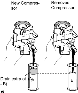
ADJUST COMPRESSOR OIL
-
When replacing the compressor with a new one, gradually discharge the refrigerant gas from the service valve. Then drain the following amount of oil from the new compressor before installation, so that the amount of oil contained in it is the same as that in the compressor to be replaced.
Tech Tips
New compressors are filled with sufficient oil for the whole cycle. Therefore, it is necessary to drain residual oil from the condenser and cooling unit.
Standard (The amount of oil inside a new compressor: 80 cc (2.7 fl.oz.)) - (The amount of oil remaining in the removed compressor) = The amount of oil to be removed when replacing the compressor Note
-
When checking the compressor oil level, observe the precautions for cooler removal/installation.
-
If a new compressor is installed without removing the volume of oil remaining in the pipes of the vehicle, the amount of oil becomes too large. This prevents heat exchange in the refrigerant cycle and causes refrigeration failure.
-
If the amount of oil remaining in the removed compressor is too small, check for oil leakage.
-
Be sure to use ZXL 200PG compressor oil.
-
-
-
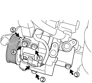
INSTALL COMPRESSOR AND MAGNETIC CLUTCH
-
Provisionally tighten the compressor and magnetic clutch with the 3 bolts.
-
Provisionally tighten compressor stay No. 1 with the bolt and nut.
-
Tighten the compressor and magnetic clutch with the 4 bolts and nut.
- Torque:
- 24.5 N*m { 250 kgf*cm, 18 ft.*lbf }
Note
Tighten the bolts in the sequence order shown in the illustration to install the compressor and magnetic clutch.
-
Connect the connector.
-
-
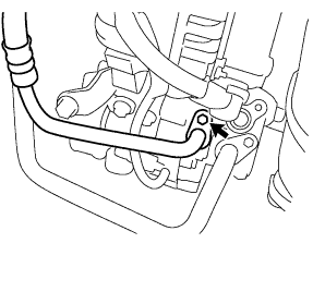
INSTALL DISCHARGE HOSE SUB-ASSEMBLY
-
Remove the attached vinyl tape from the hose.
-
Apply sufficient compressor oil to 2 new O-rings and the fitting surface of the compressor and magnetic clutch.
Compressor oil ZXL 200PG or equivalent -
Install the 2 O-rings onto the discharge hose sub-assembly.
-
Install the discharge hose sub-assembly onto the compressor and magnetic clutch with the bolt.
- Torque:
- 9.8 N*m { 100 kgf*cm, 87 in.*lbf }
-
-
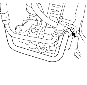
INSTALL SUCTION HOSE SUB-ASSEMBLY
-
Remove the attached vinyl tape from the hose.
-
Apply sufficient compressor oil to 2 new O-rings and the fitting surface of the compressor and magnetic clutch.
Compressor oil ZXL 200PG or equivalent -
Install the 2 O-rings onto the suction hose sub-assembly.
-
Install the suction hose sub-assembly onto the compressor and magnetic clutch with the bolt.
- Torque:
- 9.8 N*m { 100 kgf*cm, 87 in.*lbf }
-
-
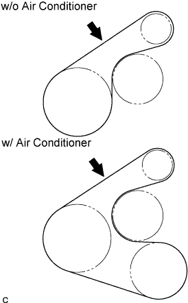
INSTALL FAN & GENERATOR V BELT
-
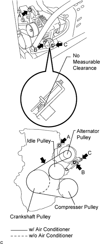
Install the fan and generator V belt.
-
Loosely tighten the B bolt until there is no measurable clearance.
-
Turn the C bolt to adjust tension of the fan and generator V belt.
-
Inspect the fan and generator V belt.
-
Tighten the B bolt.
- Torque:
- 34 N*m { 347 kgf*cm, 25 ft.*lbf }
-
Tighten the A bolt.
- Torque:
- 49 N*m { 500 kgf*cm, 36 ft.*lbf }
-
Visually check the generator wiring and listen for abnormal noise.
-
Inspect the discharge warning light circuit.
-
-
INSPECT FAN & GENERATOR V BELT
-

Visually check the belt for excessive wear, frayed cords etc.
If any defect is found, replace the belt.
Tech Tips
Cracks on the rib side of a belt are considered acceptable. If the belt has chunks missing from the ribs, it should be replaced.
-
Check the belt deflection by pressing on the belt at the points indicated by the arrow marks in the illustration.
Deflection Item Specified Condition New belt 7 to 8 mm (0.28 to 0.31 in.) Used belt 9 to 11 mm (0.35 to 0.43 in.) If the belt deflection is not as specified, adjust it.
Tech Tips
-
The most appropriate force for adjustment above is 98 N (10 kgf, 22 lbf).
-
"New belt" refers to a belt which has been used on a running engine less than 5 minutes.
-
"Used belt" refers to a belt which has been used on a running engine for 5 minutes or more.
-
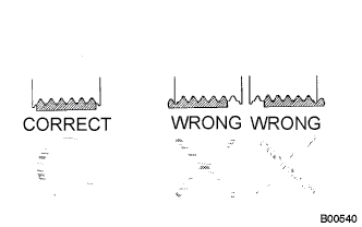
After installing a belt, check that it fits properly in the ribbed grooves.
-
Check with your hand to confirm that the belt has not slipped out of the groove on the bottom of the pulley.
-
After installing a new belt, run the engine for about 5 minutes and recheck the belt tension.
-
-
Adjust fan and generator V belt tension.
-
Loosen the A bolt.
-
Loosen the B bolt.
-
Loosely tighten the B bolt until there is no measurable clearance.
-
Turn the C bolt to adjust tension of the fan and generator V belt.
-
Tighten the B bolt.
- Torque:
- 34 N*m { 347 kgf*cm, 25 ft.*lbf }
-
Tighten the A bolt.
- Torque:
- 49 N*m { 500 kgf*cm, 36 ft.*lbf }
-
-
Visually check alternator wiring and listen for abnormal noises.
-
Check that the wiring is in good condition.
-
Check that there is no abnormal noise from the generator while the engine is running.
-
-
Inspect discharge warning light circuit.
-
Turn the ignition switch to the ON position. Check that the discharge warning light comes on.
-
Start the engine. Check that the light goes off.
-
-
-
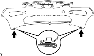
INSTALL FRONT BUMPER COVER
-
Install the 2 clips.
-
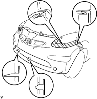
Engage the 13 claws and install the front bumper cover.
-
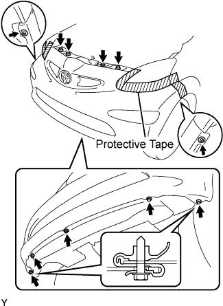
Tighten the 3 bolts and 5 screws.
-
Install the 3 clips.
-
Remove the protective tape.
-
-
CONNECT CABLE TO NEGATIVE BATTERY TERMINAL
- Torque:
- 5.4 N*m { 55 kgf*cm, 48 in.*lbf }
-
CHARGE REFRIGERANT
- SST
- 07110-58060 ( 07117-58080, 07117-58090, 07117-78050, 07117-88060, 07117-88070, 07117-88080 )
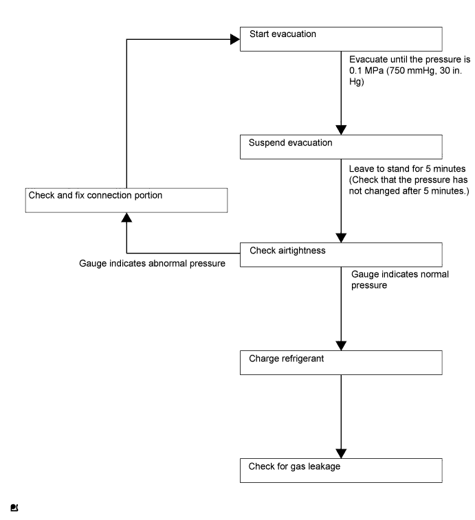
Note
Be sure to charge refrigerant in accordance with equipment manual.
-
Perform vacuum purging using a vacuum pump.
-
Charge refrigerant HFC-134a (R134a).
Standard 420 to 480g (14.81 to 16.93oz.) for IKR-FE 470 to 530g (16.58 to 18.69oz.) for 2WZ-TV Note
Do not start the engine before charging it with refrigerant as the cooler compressor doesn't work properly without sufficient refrigerant. This could cause the compressor to overheat.
Tech Tips
-
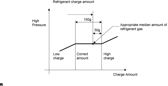
The relationship between refrigerant charge amount and pressure is as follows.
-
Correct charging amount is approximately 450g.
-
High Charge Range:
If refrigerant is overcharged, pressure rises on the high-pressure side. High-pressure cut off frequently occurs. This causes insufficient cooling performance and also insufficient compressor lubrication.
-
Low Charge Range:
Shortage of refrigerant causes insufficient cooling performance and low circulation of refrigerant oil, which shortens compressor life. Operation with insufficient coolant raises refrigerant temperature and causes heat deterioration of rubber seals and hoses. Cracking and thus refrigerant leakage may occur.
-
Install the caps onto the service valves on the refrigerant line.
-
-
WARM UP ENGINE
Note
Warm up the engine at less than 2,000 rpm for 1 minute or more after charging it with refrigerant.
-
CHECK FOR REFRIGERANT LEAKAGE
-
After recharging the refrigerant gas, check for refrigerant gas leakage using a halogen leak detector.
-
Perform the operation as follows:
-
Stop the engine.
-
Secure good ventilation (the gas leak detector may react to volatile gases other than refrigerant, such as evaporated gasoline or exhaust gas).
-
Repeat the test 2 or 3 times.
-
Make sure that some refrigerant remains in the refrigeration system.
When compressor is off: approximately 392 to 588 kPa (4 to 6 kgf*cm2, 57 to 85 psi)
Tech Tips
It is impossible for the above pressure to be maintained if there is leakage.
-
-
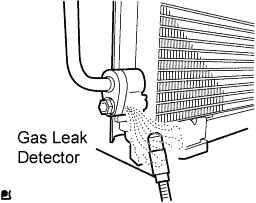
Using a gas leak detector, check the refrigerant line, especially the connecting points, for leakage.
-
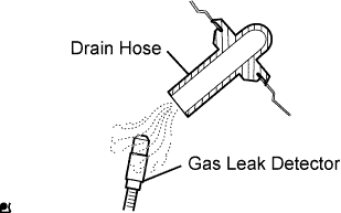
Bring the gas leak detector close to the drain hose before performing the test.
Tech Tips
-
After the blower motor has stopped, leave the cooling unit for at least 15 minutes.
-
Place the gas leak detector sensor under the drain hose.
-
When bringing the gas leak detector close to the drain hose, make sure that the gas leak detector does not react to the volatile gases.
If such a reaction is unavoidable, the vehicle must be lifted up.
-
-
If a gas leak is not detected from the drain hose, remove the blower motor from the cooling unit. Insert the gas leak detector sensor into the unit and perform the test.
-
Disconnect the pressure switch connector and leave it for approximately 20 minutes. Bring the gas leak detector close to the pressure switch and perform the test.
-