BLOWER MOTOR REMOVAL

-
REMOVE STEERING COLUMN ASSEMBLY
-
REMOVE INSTRUMENT PANEL BRACE SUB-ASSEMBLY NO. 1
-
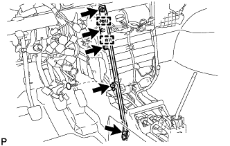
Remove the clip and fold back the floor carpet.
-
Disengage the 2 clamps.
-
Remove the 2 wire harness clamp bolts.
-
Remove the bolt, screw, nut and instrument panel brace sub-assembly No. 1.
-
-
REMOVE TRANSPONDER KEY ECU ASSEMBLY
-
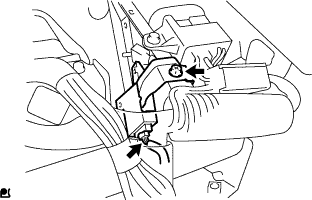
Remove the bolt.
-
Disconnect the connector and remove the transponder key ECU assembly.
-
-
REMOVE DOOR CONTROL WITH RECEIVER ECU ASSEMBLY

-
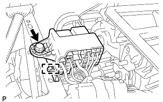
Disconnect the connector.
-
Remove the bolt and door control with receiver ECU assembly.
-
-
SEPARATE CONNECTOR HOLDER

-
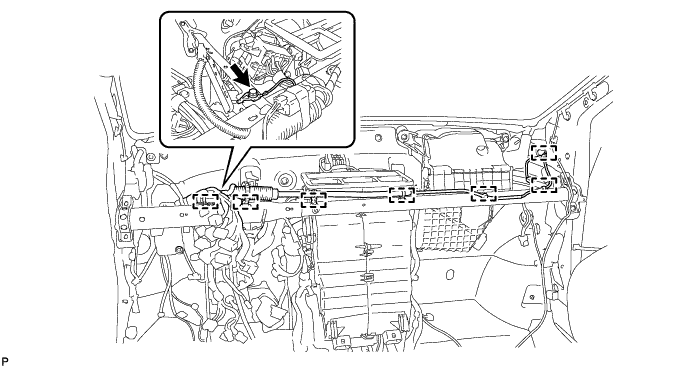
Remove the screw and separate the connector holder.
-
-
SEPARATE RELAY BLOCK ASSEMBLY
-
Remove the screw.
-
Disengage the clamp and separate the relay block assembly.
-
-
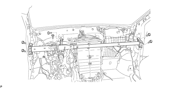
REMOVE INSTRUMENT PANEL REINFORCEMENT
-
Disengage the 7 clamps.
-
Remove the screw.
-
Remove the 6 bolts and instrument panel reinforcement.
-
-
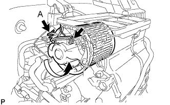
REMOVE BLOWER FAN MOTOR
-
Disconnect the connector.
-
While pressing down portion A, disengage the claw and remove the blower fan motor by turning it counterclockwise.
-