HEATER CONTROL ASSEMBLY INSTALLATION

-
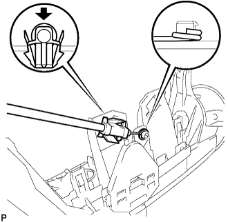
INSTALL AIR INLET DAMPER CONTROL CABLE SUB-ASSEMBLY (for LHD)
-
Install the cable ring and clamp of the air inlet cable, as shown in the illustration.
-
-
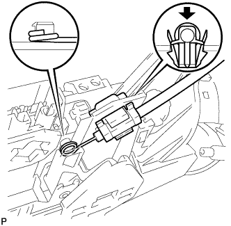
INSTALL AIR INLET DAMPER CONTROL CABLE SUB-ASSEMBLY (for RHD)
-
Install the cable ring and clamp of the air inlet cable, as shown in the illustration.
-
-
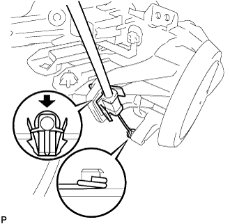
INSTALL DEFROSTER DAMPER CONTROL CABLE SUB-ASSEMBLY
-
Install the cable ring and clamp of the defroster cable, as shown in the illustration.
-
-
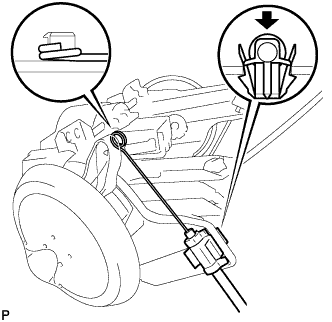
INSTALL AIR MIX DAMPER CONTROL CABLE SUB-ASSEMBLY
-
Install the cable ring and clamp of the air mix cable, as shown in the illustration.
-
-
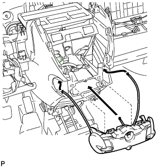
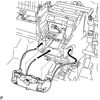
INSTALL HEATER CONTROL ASSEMBLY (for LHD)
Note
Do not bend the cable when installing the heater control assembly.
-
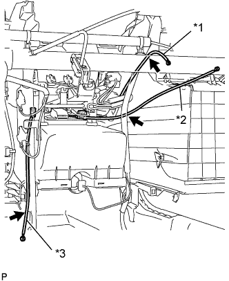
Insert each cable into the instrument panel.
-
Text in Illustration *1 Defroster Cable *2 Air Inlet Cable *3 Air Mix Cable Pass the white air inlet cable between the instrument panel and wire harness.
-
Pass the black air mix cable between the instrument panel and wire harness.
-
Pass the blue defroster cable between the instrument panel reinforcement and wire harness, and then outside the wire harness clamp.
-
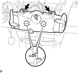
Engage the 2 claws and install the heater control assembly with the 2 screws.
-
-
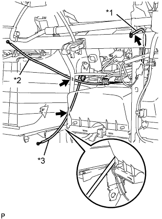
INSTALL HEATER CONTROL ASSEMBLY (for RHD)
Note
Do not bend the cable when installing the heater control assembly.
-
Insert the cable into the instrument panel.
-
Text in Illustration *1 Defroster Cable *2 Air Inlet Cable *3 Air Mix Cable Pass the white air inlet cable through the wire harness.
-
Pass the black air mix cable between the instrument panel and brace.
-
Pass the blue defroster cable between the instrument panel reinforcement and wire harness, and then outside the wire harness clamp.
-
Engage the 2 claws and install the heater control assembly with the 2 screws.
-
-
SET HEATER CONTROL ASSEMBLY
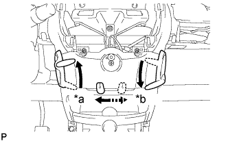
Text in Illustration *a LHD *b RHD
-
Make sure that the levers are placed in the position shown in the illustration.
-
-
CONNECT DEFROSTER DAMPER CONTROL CABLE SUB-ASSEMBLY
-
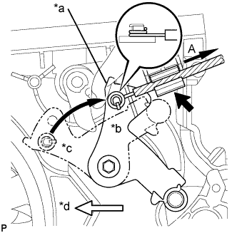
Text in Illustration *a Mode Link *b DEF *c FACE *d Front Side Turn the mode link to the DEF position.
-
Install the cable ring onto the motor link.
-
Hold the mode wheel knob of the heater control and install the defroster cable onto the clamp while pulling it in the direction indicated by arrow A.
Note
Make sure that the air mix lever knob operates correctly. Also, confirm that there is no reverse movement of the knob at either end.
-
-
CONNECT AIR MIX DAMPER CONTROL CABLE SUB-ASSEMBLY
-
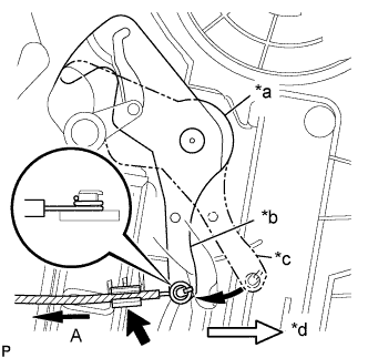
Text in Illustration *a Temperature Control Link *b COOL *c WARM *d Front Side Turn the temperature control link to the MAX-cool position.
-
Install the cable ring onto the temperature control link.
-
Hold the mode wheel knob of the heater control and install the mode cable onto the clamp while pulling it in the direction indicated by arrow A.
Note
Make sure that the air mix lever knob operates correctly. Also, confirm that there is no reverse movement of the knob at either end.
-
-
CONNECT AIR INLET DAMPER CONTROL CABLE SUB-ASSEMBLY
-
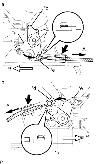
Text in Illustration *a LHD *b RHD *c Air Inlet Control Link *d FRESH *e RECIRCULATION *f Front Side Turn the air inlet control link to the RECIRCULATION position.
-
Turn the air inlet control link to the FRESH AIR position.
-
Install the cable ring onto the air inlet control link.
-
Hold the air inlet lever knob of the heater control and install the air inlet cable onto the clamp while pulling it in the direction indicated by arrow A.
Note
Make sure that the air inlet lever knob operates correctly. Also, confirm that there is no reverse movement of the knob at either end.
-
-
INSTALL INSTRUMENT PANEL ASSEMBLY