HEATER CONTROL ASSEMBLY INSTALLATION

-
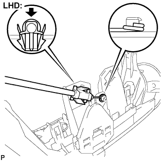
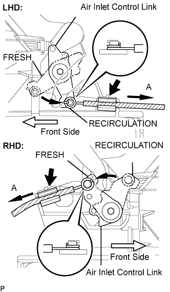
INSTALL AIR INLET DAMPER CONTROL CABLE SUB-ASSEMBLY (for LHD)
-
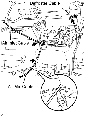
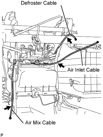
Install the cable ring and clamp of the air inlet cable, as shown in the illustration.
-
-
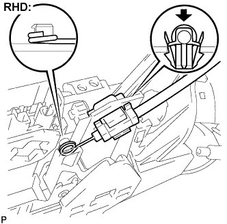
INSTALL AIR INLET DAMPER CONTROL CABLE SUB-ASSEMBLY (for RHD)
-
Install the cable ring and clamp of the air inlet cable, as shown in the illustration.
-
-
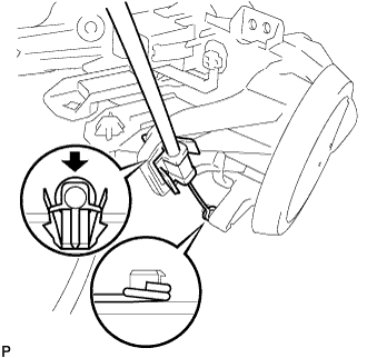
INSTALL DEFROSTER DAMPER CONTROL CABLE SUB-ASSEMBLY
-
Install the cable ring and clamp of the defroster cable, as shown in the illustration.
-
-
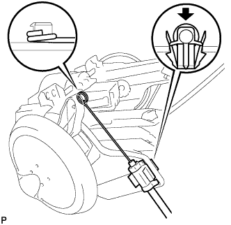
INSTALL AIR MIX DAMPER CONTROL CABLE SUB-ASSEMBLY
-
Install the cable ring and clamp of the air mix cable, as shown in the illustration.
-
-
INSTALL HEATER CONTROL ASSEMBLY (for LHD)
Note
Do not bend the cable when installing the heater control assembly.
-
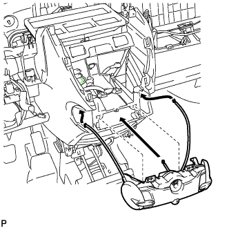
Insert each cable into the instrument panel.
-
Pass the white air inlet cable between the instrument panel and wire harness.
-
Pass the black air mix cable between the instrument panel and wire harness.
-
Pass the blue defroster cable between the instrument panel reinforcement and wire harness, and then outside the wire harness clamp.
-
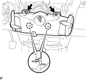
Engage the 2 claws and install the heater control assembly with the 2 screws.
-
-
INSTALL HEATER CONTROL ASSEMBLY (for RHD)
Note
Do not bend the cable when installing the heater control assembly.
-
Insert the cable into the instrument panel.
-
Pass the white air inlet cable through the wire harness.
-
Pass the black air mix cable between the instrument panel and brace.
-
Pass the blue defroster cable between the instrument panel reinforcement and wire harness, and then outside the wire harness clamp.
-
Engage the 2 claws and install the heater control assembly with the 2 screws.
-
-
SET HEATER CONTROL ASSEMBLY
-
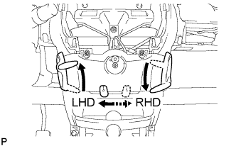
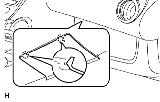
Make sure that the levers are placed in the position shown in the illustration.
-
-
CONNECT DEFROSTER DAMPER CONTROL CABLE SUB-ASSEMBLY
-
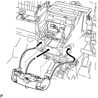
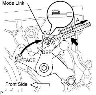
Turn the mode link to the DEF position.
-
Install the cable ring onto the motor link.
-
Hold the mode wheel knob of the heater control and install the defroster cable onto the clamp while pulling it in the direction indicated by arrow A.
Note
Make sure that the air mix lever knob operates correctly. Also, confirm that there is no reverse movement of the knob at either end.
-
-
CONNECT AIR MIX DAMPER CONTROL CABLE SUB-ASSEMBLY
-
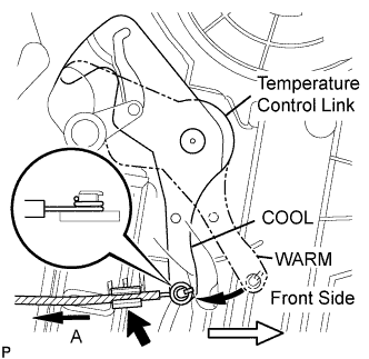
Turn the temperature control link to the MAX-cool position.
-
Install the cable ring onto the temperature control link.
-
Hold the mode wheel knob of the heater control and install the mode cable onto the clamp while pulling it in the direction indicated by arrow A.
Note
Make sure that the air mix lever knob operates correctly. Also, confirm that there is no reverse movement of the knob at either end.
-
-
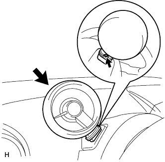
CONNECT AIR INLET DAMPER CONTROL CABLE SUB-ASSEMBLY
-
Turn the air inlet control link to the RECIRCULATION position.
-
Turn the air inlet control link to the FRESH AIR position.
-
Install the cable ring onto the air inlet control link.
-
Hold the air inlet lever knob of the heater control and install the air inlet cable onto the clamp while pulling it in the direction indicated by arrow A.
Note
Make sure that the air inlet lever knob operates correctly. Also, confirm that there is no reverse movement of the knob at either end.
-
-
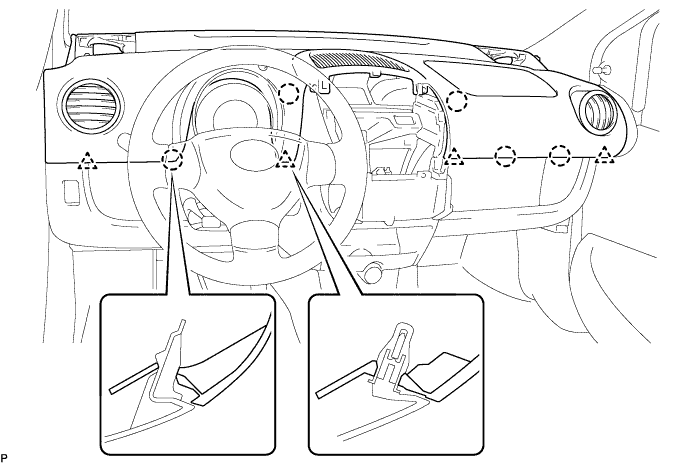
INSTALL INSTRUMENT PANEL ASSEMBLY
-
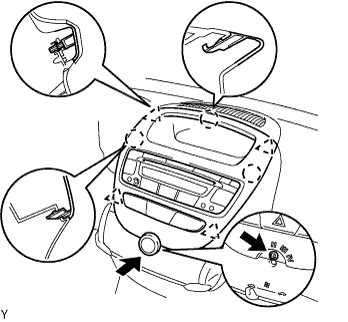
Engage the 4 clips and 5 claws and install the instrument panel assembly.
Note
Make sure that there are no gaps between the instrument panel upper and instrument panel lower panel.
-
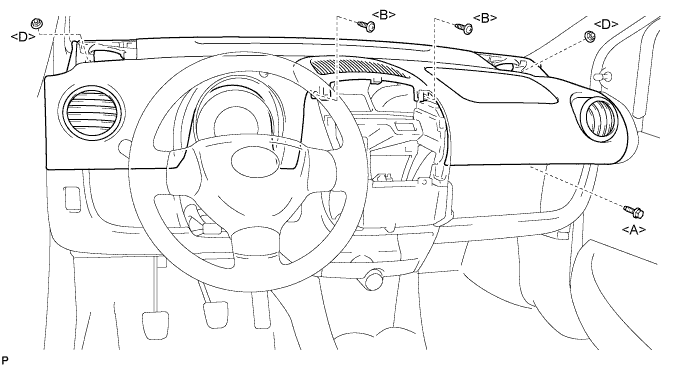
Install the bolt <A>, 2 nuts <D> and 2 screws <B>.
- Torque:
- 18 N*m { 184 kgf*cm, 13 ft.*lbf, for bolt <A> }
- 6.0 N*m { 61 kgf*cm, 53 in.*lbf, for nut <D> }
-
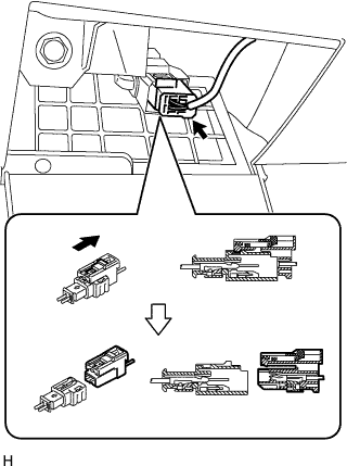
Connect the airbag connector, as shown in the illustration.
-
Engage the 2 claws and close the cover.
-
-
INSTALL INSTRUMENT CLUSTER FINISH PANEL SUB-ASSEMBLY CENTER
-
Connect the connectors.
-
Engage the 4 clips and 3 claws and install the instrument cluster finish panel center.
-
Install the screw.
-
Install the control knob.
-
-
INSTALL FRONT NO. 1 SPEAKER ASSEMBLY
-
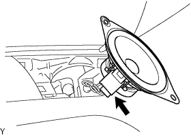
Connect the connector.
-
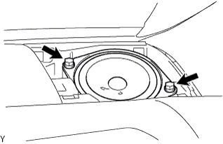
Install the 2 screws.
-
-
INSTALL INSTRUMENT PANEL SPEAKER PANEL SUB-ASSEMBLY NO. 2
-
Engage the 2 claws.
-
-
INSTALL FRONT NO. 1 SPEAKER ASSEMBLY
-
INSTALL INSTRUMENT PANEL SPEAKER PANEL SUB-ASSEMBLY NO. 1
-
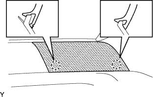
INSTALL FRONT PILLAR GARNISH RH (w/ Curtain Shield Airbag)
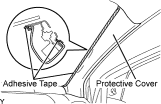
-
Remove the adhesive tape and protective cover.
-
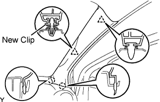
Install a new clip.
-
Engage the 2 claws and 2 clips, and install the front pillar garnish.
-
-
INSTALL FRONT PILLAR GARNISH LH (w/ Curtain Shield Airbag)
Tech Tips
Use the same procedure as for the RH side.
-
INSTALL FRONT PILLAR GARNISH RH (w/o Curtain Shield Airbag)
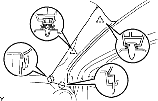
-
Engage the 2 claws and 2 clips, and install the front pillar garnish.
-
-
INSTALL FRONT PILLAR GARNISH LH (w/o Curtain Shield Airbag)
Tech Tips
Use the same procedure as for the RH side.
-
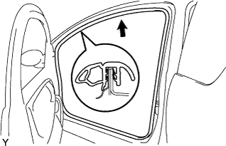
INSTALL FRONT DOOR OPENING TRIM WEATHERSTRIP LH
-
Install the front door opening trim weatherstrip.
-
-
INSTALL FRONT DOOR OPENING TRIM WEATHERSTRIP RH
-
INSTALL TACHOMETER ASSEMBLY (w/ Tachometer)
-
Install the tachometer with the bolt.
- Torque:
- 6.5 N*m { 66 kgf*cm, 58 in.*lbf }
-
Connect the connector.
-
-
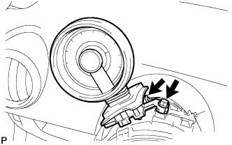
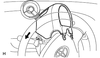
INSTALL STEERING COLUMN UPPER COVER
-
Install the steering column cover upper, as shown in the illustration (w/ tachometer).
-
While turning the steering wheel to the right and left, engage the 4 claws and install the steering column cover upper with the 2 screws.
- Torque:
- 2.0 N*m { 20 kgf*cm, 18 in.*lbf }
-
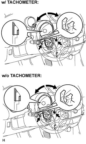
Tighten the screw behind the tachometer (w/ tachometer).
Note
Tighten the screw if the tachometer has been extended and the column cover has been removed.
- Torque:
- 9.0 N*m { 92 kgf*cm, 80 in.*lbf }
-
-
CONNECT CABLE TO NEGATIVE BATTERY TERMINAL
- Torque:
- 5.4 N*m { 55 kgf*cm, 48 in.*lbf }
-
INSPECT SRS WARNING LIGHT