HEATER CONTROL ASSEMBLY INSPECTION

-
INSPECT HEATER CONTROL ASSEMBLY
-
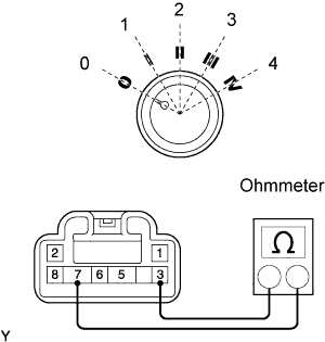
Check the heater blower switch resistance.
-
Using an ohmmeter, measure the resistance and check the results in accordance with the values in the table below.
Standard Resistance Blower Switch Position Tester Connection Specified Condition 0 3 - 5 - 6 - 7 - 8 10 KΩ or higher 0 - 1 3 - 5 - 6 - 7 - 8 10 KΩ or higher 1 3 - 7 Below 1 Ω 1 - 2 3 - 7 - 8 Below 1 Ω 2 3 - 7 - 8 Below 1 Ω 2 - 3 3 - 6 - 7 - 8 Below 1 Ω 3 3 - 6 - 7 Below 1 Ω 3 - 4 3 - 5 - 6 - 7 Below 1 Ω 4 3 - 5 - 7 Below 1 Ω If the result is not as specified, replace the heater blower switch.
-
-
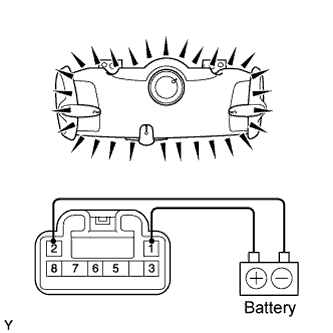
Check the illumination operation.
-
Connect the positive (+) lead from the battery to terminal 1 (P) and the negative (-) lead to terminal 2 (P), then check that the 2 bulbs illuminate.
Standard Bulbs illuminate If the result is not as specified, check for faulty bulbs.
-
-
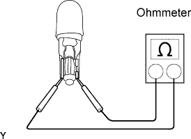
Inspect the bulb.
-
Inspect continuity of the bulb by connecting the tester, as shown in the illustration.
Standard Resistance Continuity If continuity exists, replace the heater blower switch.
If no continuity exists, replace the bulb.
-
-