AIRBAG SYSTEM SRS Warning Light Remains ON
DESCRIPTION
The SRS warning light is located on the combination meter. When the SRS (Supplemental Restraint System) is functioning normally, the SRS warning light comes on for approximately 6 seconds after the ignition switch is turned from the LOCK position to the ON position, and then turns off automatically.
If the continuous illumination is caused by a problem such as a malfunction in the SRS warning light circuit, no DTCs are set.
The SRS warning light remains illuminated while the airbag cut-off switch is off.
WIRING DIAGRAM
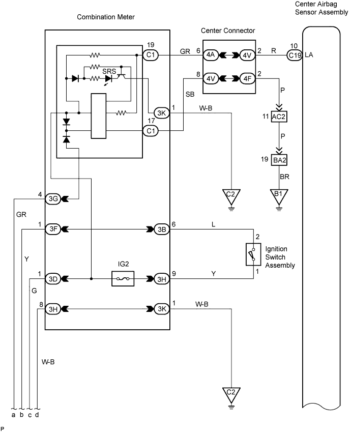
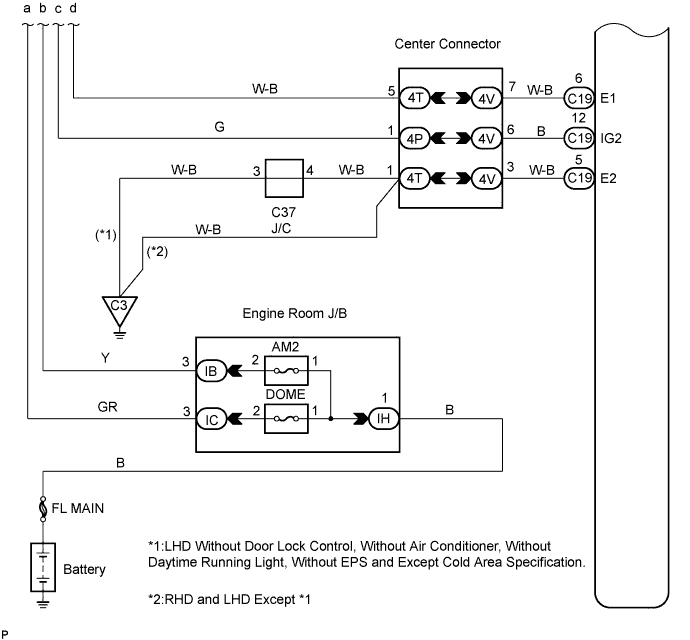
INSPECTION PROCEDURE
Note
In order to prevent unexpected airbag deployment, disconnect the following connectors before inspecting parts such as wire harnesses, if the application of tester probes to the center airbag sensor assembly connector is necessary.
-
Turn the ignition switch to the LOCK position.
-
Disconnect the negative (-) terminal cable from the battery, and wait for at least 90 seconds.
-
Disconnect the connectors from the center airbag sensor assembly.
-
Disconnect the connectors from the steering pad.
-
Disconnect the connector from the front passenger airbag assembly.
-
Disconnect the connector from the front seat outer belt assembly LH.
-
Disconnect the connector from the front seat outer belt assembly RH.
Tech Tips
Skip the following steps if side and curtain shield airbags are not fitted.
-
Disconnect the connector from the front seat airbag assembly LH.
-
Disconnect the connector from the front seat airbag assembly RH.
-
Disconnect the connector from the curtain shield airbag assembly LH.
-
Disconnect the connector from the curtain shield airbag assembly RH.
PROCEDURE
-
CHECK BATTERY
-
Measure the battery voltage.
Standard Voltage 11 to 14 V
NG 
REPAIR OR REPLACE BATTERY
OK 
-
-
CHECK CONNECTION OF CONNECTOR
-
Disconnect the negative (-) terminal cable from the battery, and wait for at least 90 seconds.
-
Check that the connectors are properly connected to the center airbag sensor assembly and combination meter.
OK The connectors are properly connected.
NG
CONNECT CONNECTOR
OK
-
-
CHECK CONNECTOR
-
Check that the connectors (on the center airbag sensor assembly side and combination meter side) are not damaged Click here.
OK The connectors are not deformed or damaged.
NG
REPAIR OR REPLACE INSTRUMENT PANEL WIRE
OK
-
-
CHECK INSTRUMENT PANEL WIRE (POWER SOURCE)
-
Disconnect the connector from the center airbag sensor assembly.
-
Connect the negative (-) terminal cable to the battery.
-
Turn the ignition switch to the ON position.
-
Measure the voltage.
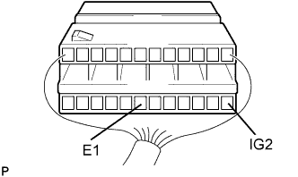
Standard Voltage Tester Connection Condition Specified Condition C19-12 (IG2) C19-6 (E1) Ignition switch ON 10 to 14 V
NG
REPAIR OR REPLACE INSTRUMENT PANEL WIRE (BATTERY - CENTER AIRBAG SENSOR ASSEMBLY)
OK
-
-
CHECK INSTRUMENT PANEL WIRE (CENTER AIRBAG SENSOR ASSEMBLY - COMBINATION METER)
-
Turn the ignition switch to the LOCK position.
-
Disconnect the connector from the combination meter.
-
Measure the resistance.
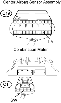
Standard Resistance Tester Connection Condition Specified Condition C19 -19 (LA) - C1-19 (SW) Always Below 1 Ω C19 -19 (LA) - Body ground Always 1 MΩ or Higher -
Connect the negative (-) terminal cable to the battery.
-
Turn the ignition switch to the ON position.
-
Measure the voltage.
Standard Voltage Tester Connection Condition Specified Condition C19 -19 (LA) - Body ground Ignition switch ON Below 1 V
NG
REPAIR OR REPLACE INSTRUMENT PANEL WIRE (CENTER AIRBAG ASSEMBLY - COMBINATION METER)
OK
-
-
CHECK FUSE (IG2, DOME, AM2)
-
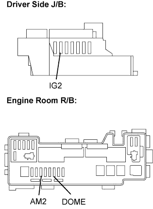
Remove the IG2 fuse from the driver side J/B.
-
Remove the DOME fuse and AM2 fuse from the engine room R/B.
-
Measure the resistance.
Standard Resistance Below 1 Ω -
Reinstall the fuses.
NG
INSPECT FOR SHORT CIRCUIT IN HARNEE AND ALL COMPONENTS CONNECTED TO FUSE
OK
-
-
INSPECT COMBINATION METER ASSEMBLY
-
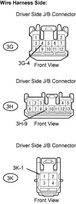
Disconnect the 3G, 3H and 3K driver side J/B connectors.
-
Measure the resistance.
Standard Resistance Tester Connection Condition Specified Condition 3K-1 - Body ground Always Below 1 Ω -
Measure the voltage.
Standard Voltage Tester Connection Condition Specified Condition 3H-9 - Body ground Ignition switch ON 10 to 14 V 3G-4 - Body ground Always 10 to 14 V -
Reinstall the driver side J/B connectors.
NG
REPAIR OR REPLACE HARNESS OR CONNECTOR
OK
-
-
CHECK CENTER AIRBAG SENSOR ASSEMBLY
-
Turn the ignition switch to the LOCK position.
-
Disconnect the negative (-) terminal cable from the battery, and wait for at least 90 seconds.
-
Replace the center airbag sensor assembly Click here.
Tech Tips
Perform the inspection using parts from a normal vehicle when possible.
-
Connect the connectors to the center airbag sensor assembly.
-
Connect the negative (-) terminal cable to the battery, and wait for at least 2 seconds.
-
Turn the ignition switch to the ON position, and wait for at least 60 seconds.
-
Clear any DTCs stored in the memory Click here.
-
Turn the ignition switch to the LOCK position.
-
Turn the ignition switch to the ON position, and wait for at least 60 seconds.
-
Check the SRS warning light operation.
OK The SRS warning light turns off 6 seconds after the ignition switch is turned to the ON position.
NG
INSPECT COMBINATION METER
OK 
REPLACE CENTER AIRBAG SENSOR ASSEMBLY
-