AIRBAG SYSTEM Source Voltage Drop
DESCRIPTION
The center airbag sensor assembly is equipped with a voltage-increase circuit (DC-DC converter) in case the source voltage of the SRS drops. When the battery voltage drops, the SRS source voltage is boosted to the necessary level by the circuit.
The diagnosis system malfunction indication for this circuit (DC-DC converter) is different from those of other circuits. When the SRS source voltage drops, the center airbag sensor assembly indicates the malfunction by blinking the SRS warning light. However, no DTCs are set.
The SRS warning light stops blinking and goes off when the SRS source voltage returns to normal.
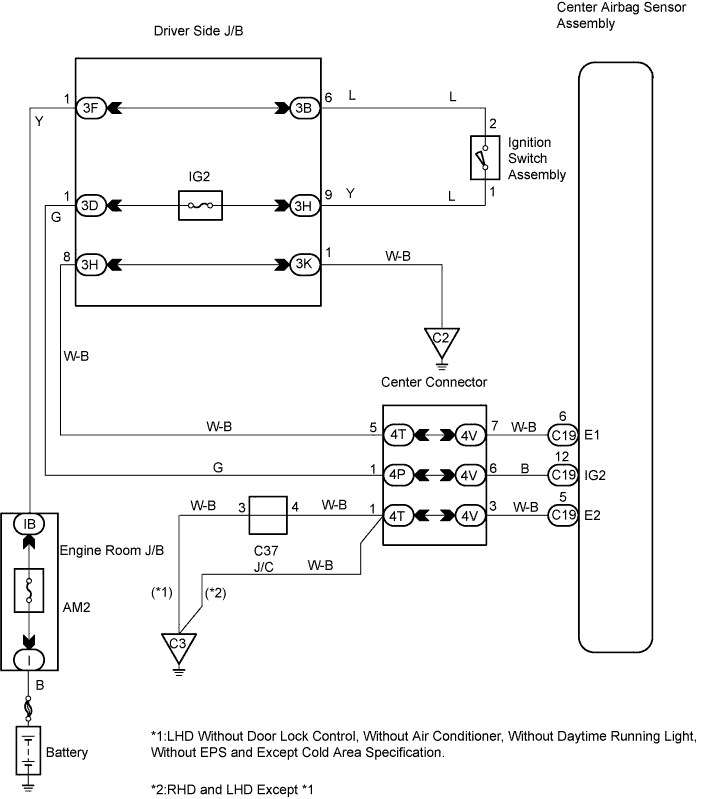
WIRING DIAGRAM
INSPECTION PROCEDURE
Note
In order to prevent unexpected airbag deployment, disconnect the following connectors before inspecting parts such as wire harnesses, if the application of tester probes to the center airbag sensor assembly connector is necessary.
-
Turn the ignition switch to the LOCK position.
-
Disconnect the negative (-) terminal cable from the battery, and wait for at least 90 seconds.
-
Disconnect the connectors from the center airbag sensor assembly.
-
Disconnect the connectors from the steering pad.
-
Disconnect the connector from the front passenger airbag assembly.
-
Disconnect the connector from the front seat outer belt assembly LH.
-
Disconnect the connector from the front seat outer belt assembly RH.
Tech Tips
Skip the following steps if side and curtain shield airbags are not fitted.
-
Disconnect the connector from the front seat airbag assembly LH.
-
Disconnect the connector from the front seat airbag assembly RH.
-
Disconnect the connector from the curtain shield airbag assembly LH.
-
Disconnect the connector from the curtain shield airbag assembly RH.
PROCEDURE
-
CHECK BATTERY
-
Measure the battery voltage.
Standard Voltage 11 to 14 V
NG 
REPAIR OR REPLACE BATTERY
OK 
-
-
CHECK CONNECTION OF CONNECTOR
-
Disconnect the negative (-) terminal cable from the battery, and wait for at least 90 seconds.
-
Check that the connectors are properly connected to the center airbag sensor assembly.
OK The connectors are properly connected.
NG
CONNECT CONNECTOR
OK
-
-
CHECK CONNECTOR
-
Check that the connectors (on the center airbag sensor assembly side) are not damaged Click here.
OK The connectors are not deformed or damaged
NG
REPAIR OR REPLACE INSTRUMENT PANEL WIRE
OK
-
-
CHECK INSTRUMENT PANEL WIRE
-
Turn the ignition switch to the ON position.
-
Measure the voltage.
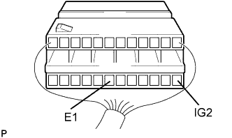
Standard Voltage Tester Connection Condition Specified Condition C19-12 (IG2) C19-6 (E1) Ignition switch ON 8 V or Higher
NG
REPAIR OR REPLACE INSTRUMENT PANEL WIRE (BATTERY - CENTER AIRBAG SENSOR ASSEMBLY)
OK
-
-
CHECK POWER SOURCE AND ELECTRICAL SYSTEM COMPONENTS
-
Turn the ignition switch to the ON position.
-
Turn on all electrical system components such as the defogger, wipers, head lamps and heater blower.
-
Measure the voltage.
Standard Voltage Tester Connection Condition Specified Condition C19-12 (IG2) C19-6 (E1) Ignition switch ON 8 V or Higher
NG
REPAIR OR REPLACE POWER SOURCE AND ELECTRICAL SYSTEM COMPONENTS
OK 
USE SIMULATION METHOD TO CHECK
-