AIRBAG SYSTEM, Diagnostic DTC:B1805, B1806, B1807, B1808

| DTC Code | DTC Name |
|---|---|
| B1805 | Short in Front Passenger Squib Circuit |
| B1806 | Open in Front Passenger Squib Circuit |
| B1807 | Short to GND in Front Passenger Side Squib Circuit |
| B1808 | Short to B+ in Front Passenger Side Squib Circuit |
DESCRIPTION
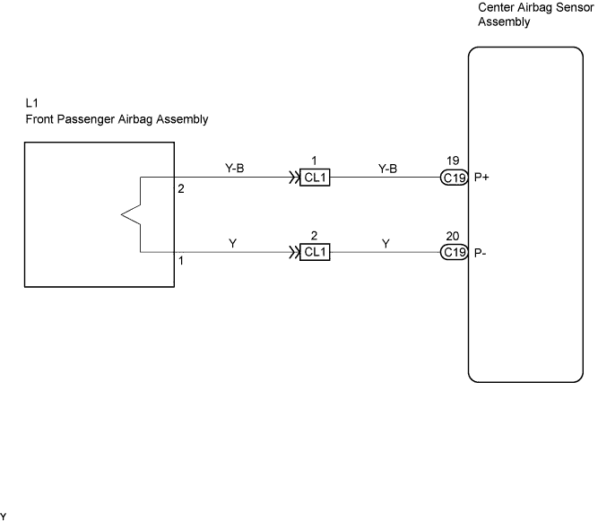
The P squib circuit consists of the center airbag sensor assembly and the front passenger airbag assembly.
The circuit signals the SRS to deploy when airbag deployment conditions are met.
These DTCs are set when a malfunction is detected in the P squib circuit.
| DTC No. | DTC Detecting Conditions | Trouble Areas |
|---|---|---|
| B1805 |
|
|
| B1806 |
|
|
| B1807 |
|
|
| B1808 |
|
|
WIRING DIAGRAM
INSPECTION PROCEDURE
Tech Tips
Perform a check mode inspection after repairing the squib system to check if the repair has done correctly Click here.
PROCEDURE
-
CHECK FRONT PASSENGER AIRBAG ASSEMBLY
- SST
- 09843-18060
-
Turn the ignition switch to the LOCK position.
-
Disconnect the negative (-) terminal cable from the battery, and wait for at least 90 seconds.
-
Disconnect the connectors from the front passenger airbag assembly.
-
Connect the white wire side of SST (resistance 2.1 Ω) to the instrument panel wire No. 3.
CAUTION:
Never connect a tester to the front passenger airbag assembly (D squib) for measurement, as this may lead to a serious injury due to airbag deployment.
Note
-
Do not forcibly insert the SST into the terminals of the connector when connecting.
-
Insert the SST straight into the terminals of the connector.
-
-
Connect the negative (-) terminal cable to the battery, and wait for at least 2 seconds.
-
Turn the ignition switch to the ON position, and wait for at least 60 seconds.
-
Clear the DTCs stored in memory Click here.
-
Turn the ignition switch to the LOCK position.
-
Turn the ignition switch to the ON position, and wait for at least 60 seconds.
-
Check the DTCs Click here.
OK DTC B1805, B1806, B1807 and B1808 are not output.
OK 
REPLACE FRONT PASSENGER AIRBAG ASSEMBLY
NG 
-
CHECK CONNECTOR
-
Turn the ignition switch to the LOCK position.
-
Disconnect the negative (-) terminal cable from the battery, and wait for at least 90 seconds.
-
Check that the instrument panel wire No. 3 connector (on the front passenger airbag assembly side) are not damaged Click here.
OK The lock button is not disengaged, and the claw of the lock is not deformed or damaged.
NG
REPLACE INSTRUMENT PANEL WIRE NO.3
OK
-
-
CHECK CONNECTION OF CONNECTOR
-
Check that the connectors are properly connected to the center airbag sensor assembly and the instrument panel wire No. 3.
OK The connectors are properly connected.
NG
CONNECT CONNECTOR
OK
-
-
CHECK INSTRUMENT PANEL WIRE NO.3
-
Disconnect the instrument panel wire No. 3 connectors from the instrument panel wire and front passenger airbag assembly.
-
Connect the negative (-) terminal cable to the battery, and wait for at least 2 seconds.
-
Turn the ignition switch to the ON position.
-
Measure the voltage.
Standard Voltage Tester Connection Condition Specified Condition L1-2 (P+) -
Body ground
Ignition switch ON Below 1 V L1-1 (P-) -
Body ground
Ignition switch ON Below 1 V -
Turn the ignition switch to the LOCK position.
-
Disconnect the negative (-) terminal cable from the battery, and wait for at least 90 seconds.
-
Measure the resistance.
Standard Resistance Tester Connection Condition Specified Condition L1-2 (P+) - L1-1 (P-) Always Below 1 Ω L1-2 (P+) -
Body ground
Always 1 MΩ or Higher L1-1 (P-) -
Body ground
Always 1 MΩ or Higher -
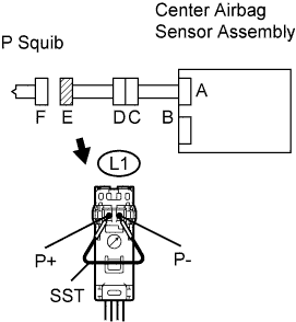
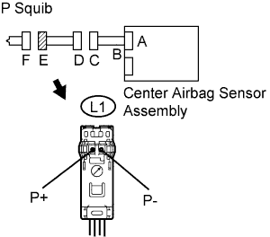
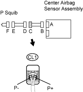
Release the activation prevention mechanism built into connector D Click here.
-
Measure the resistance.
Standard Resistance Tester Connection Condition Specified Condition L1-2 (P+) - L1-1 (P-) Always 1 MΩ or Higher
NG
REPLACE INSTRUMENT PANEL WIRE NO.3
OK
-
-
CHECK INSTRUMENT PANEL WIRE (P SQUIB CIRCUIT)
-
Disconnect the instrument panel wire connector from the center airbag sensor assembly.
-
Connect the negative (-) terminal cable to the battery, and wait for at least 2 seconds.
-
Turn the ignition switch to the ON position.
-
Measure the voltage.
Standard Voltage Tester Connection Condition Specified Condition CL1-1 (P+) -
Body ground
Ignition switch ON Below 1 V CL1-2 (P-) -
Body ground
Ignition switch ON Below 1 V -
Turn the ignition switch to the LOCK position.
-
Disconnect the negative (-) terminal cable from the battery, and wait for at least 90 seconds.
-
Measure the resistance.
Standard Resistance Tester Connection Condition Specified Condition CL1-1 (P+) - CL1-2 (P-) Always Below 1 Ω CL1-1 (P+) -
Body ground
Always 1 MΩ or Higher CL1-2 (P-) -
Body ground
Always 1 MΩ or Higher -
Release the activation prevention mechanism built into connector B Click here.
-
Measure the resistance.
Standard Resistance Tester Connection Condition Specified Condition CL1-1 (P+) - CL1-2 (P-) Always 1 MΩ or Higher
NG
REPLACE INSTRUMENT PANEL WIRE
OK 
REPLACE CENTER AIRBAG SENSOR ASSEMBLY
-