AIR CONDITIONING UNIT (for 2WZ-TV) REMOVAL

Tech Tips
Use the same procedure for both the RH and LH sides.
-
PRECAUTION
-
DISCHARGE REFRIGERANT FROM REFRIGERATION SYSTEM
-
Start up the engine.
-
Switch A/C ON.
-
Turn the blower switch to ON.
-
Operate the cooler compressor with an engine speed of approximately 1,000 rpm for 5 to 6 minutes to circulate the refrigerant and collect the compressor oil remaining in each component into the cooler compressor.
-
Stop the engine.
-
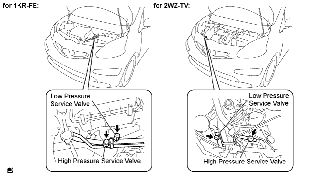
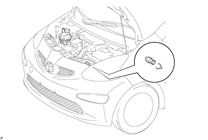
Remove the caps from the service valves on the refrigerant line.
-
Connect the Freon collection/recycling device to discharge the refrigerant gas remaining in the refrigeration system.
Note
Use the Freon collection/recycling device in accordance with the manufacturer's instruction manual.
-
-
BOLTS, SCREWS AND NUTS TABLE
Tech Tips
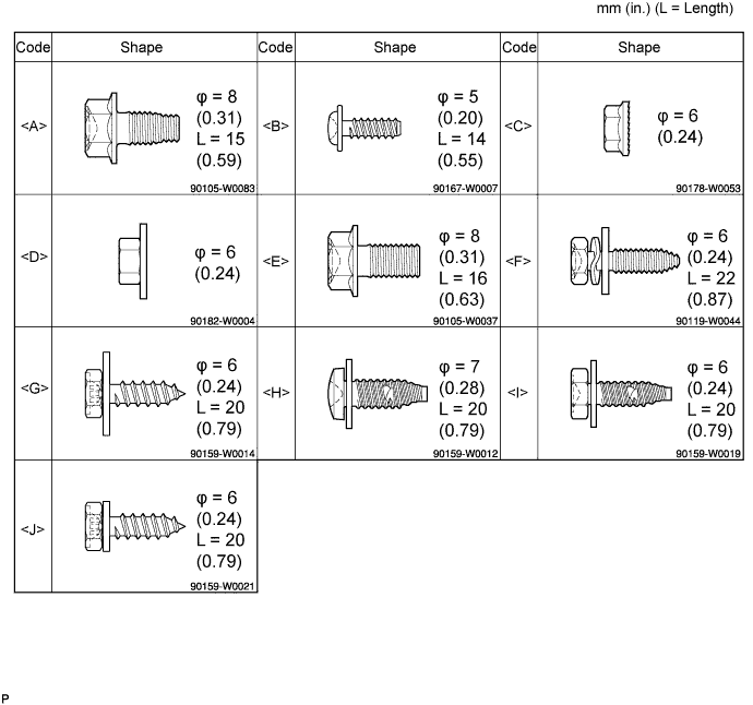
All bolts, screws and nuts relevant to installing and removing the instrument panel are shown, along with their alphabetic codes, in the table below.
-
POSITION FRONT WHEELS FACING STRAIGHT AHEAD
-
DISCONNECT CABLE FROM NEGATIVE BATTERY TERMINAL
Wait for at least 90 seconds after disconnecting the cable to prevent the airbag from working.
-
DRAIN ENGINE COOLANT
Note
To avoid the danger of being burned, do not remove the reservoir tank cap sub-assembly while the engine and radiator assembly are still hot. Thermal expansion will cause hot engine coolant and steam to blow out from the radiator assembly.
-
Remove the drain plug and clip, then drain the engine coolant.
-
Disconnect the radiator by uncoupling the radiator hose No.2.
-
Remove the hose clamp, disconnect the water by-pass hose.
-
Remove the reservoir tank cap sub-assembly.
-
-
REMOVE FRONT WIPER ARM HEAD CAP
-
Using a screwdriver with its tip wrapped in protective tape, remove the front wiper arm head cap.
-
-
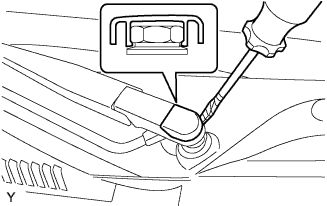
REMOVE FRONT WIPER ARM LH
-
Operate the wiper, then stop the windshield wiper motor assembly in the automatic stop position.
-
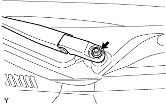
Remove the nut and front wiper main arm.
-
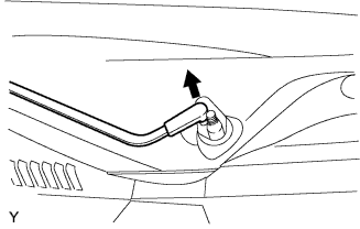
Disengage the meshing of the secondary arm from the front wiper motor and link assembly.
Note
Do not bend the secondary arm when removing it.
-
-
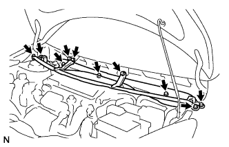
REMOVE HOOD TO COWL TOP SEAL

-
Disengage the 8 clips and remove the hood to cowl top seal.
-
-
REMOVE COWL TOP VENTILATOR LOUVER LH
-
Remove the clip.
-
Disengage the 9 claws and remove the cowl top ventilator louver LH.
-
Disconnect the washer hose.
-
-
REMOVE COWL TOP VENTILATOR LOUVER RH

-
Remove the clip.
-
Disengage the 8 claws and remove the cowl top ventilator louver RH.
-
Disconnect the washer hose.
-
-
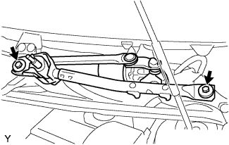
REMOVE FRONT WIPER MOTOR AND LINK ASSEMBLY
-
Remove the 2 bolts.
-
Disconnect the connector and remove the front wiper motor and link assembly.
-
-
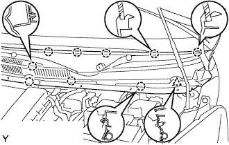
REMOVE COWL TOP PANEL OUTER
-
Remove the 10 bolts and cowl top panel outer.
-
-
REMOVE BATTERY
-
Loosen the nut and disconnect the battery positive terminal.
-
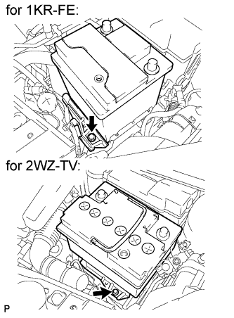
Remove the bolt and battery clamp.
-
Remove the battery.
-
-
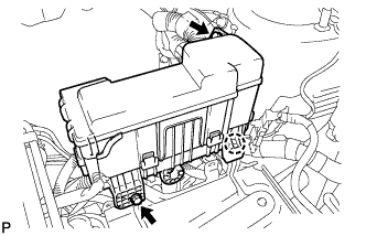
SEPARATE ENGINE ROOM RELAY BLOCK
-
Remove the 2 bolts.
-
Disengage the claw and separate the engine room relay block.
-
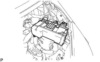
Provisionally set the relay block to the hood support rod.
-
-
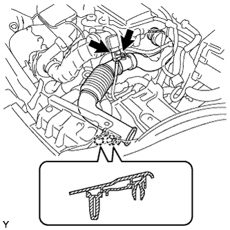
REMOVE AIR CLEANER INLET
-
Disconnect the connector.
-
Disengage the 2 claws.
-
Remove the air cleaner inlet.
-
-
DISCONNECT SUCTION HOSE SUB-ASSEMBLY

-
Remove the bolt and disconnect the suction hose and air conditioning tube.
Note
Seal the openings of the disconnected parts using vinyl tape to prevent moisture and foreign matter from entering.
-
-
DISCONNECT HEATER WATER INLET HOSE

-
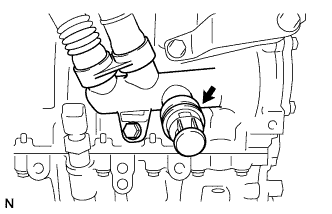
Using pliers, grip the claws of the clip, slide the clip and disconnect the heater water inlet hose from the heater unit.
-
-
DISCONNECT HEATER WATER OUTLET HOSE

-
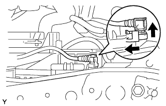
Remove the clip.
-
Disconnect the heater water outlet hose from the heater unit.
-
-
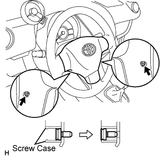
REMOVE HORN BUTTON ASSEMBLY
-
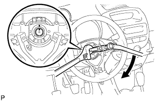
Place the front wheels facing straight ahead.
-
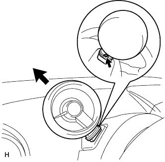
Using "Torx" socket wrench T30, loosen the 2 screws until the screw thread catches on the screw case.
-
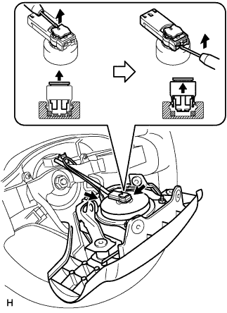
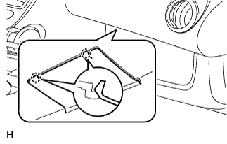
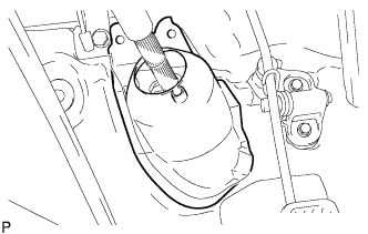
Pull the steering pad out of the steering wheel and support the steering pad with one hand, as shown in the illustration.
Note
When removing the steering pad, do not pull the airbag wire harness.
-
Disconnect the horn connector.
-
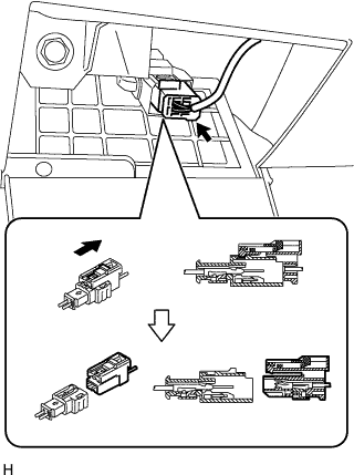
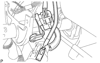
Disconnect the airbag connector, as shown in the illustration.
Note
When handling the airbag connector, do not damage the airbag wire harness.
-
Remove the steering pad.
-
-
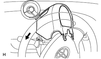
REMOVE STEERING WHEEL ASSEMBLY
-
Remove the nut and put matchmarks on the steering wheel assembly and steering main shaft.
-
Using SST, remove the steering wheel assembly.
- SST
- 09950-50013 ( 09951-05010, 09952-05010, 09953-05020, 09954-05021 )
-
-
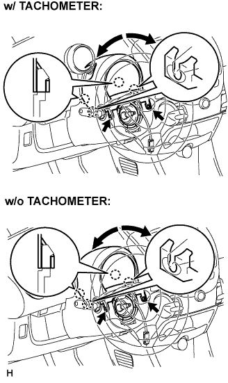
REMOVE STEERING COLUMN UPPER COVER
-
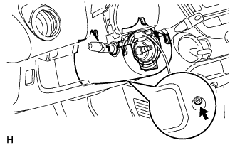
Remove the 2 screws while turning the steering wheel to the right and left.
-
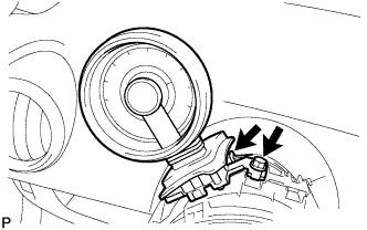
Disengage the 4 claws and remove the steering column cover upper.
-
Remove the steering column cover upper, as shown in the illustration (w/ tachometer).
-
If the steering column cover upper is difficult to remove, loosen the screw behind the tachometer, pull up and extend the tachometer, and then remove the steering cover upper (w/ tachometer).
-
-
REMOVE STEERING COLUMN LOWER COVER
-
Remove the screw and steering column lower cover.
-
-
REMOVE TACHOMETER ASSEMBLY (w/ Tachometer)
-
Disconnect the connector.
-
Remove the bolt and tachometer.
-
-
REMOVE SPIRAL CABLE SUB-ASSEMBLY
-
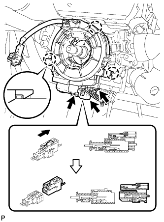
Disconnect the horn connector.
-
Disconnect the airbag connector, as shown in the illustration.
Note
When handling the airbag connector, do not damage the airbag wire harness.
-
Disconnect the steering angle sensor connector (w/ VSC).
-
Disengage the 3 claws and remove the spiral cable.
-
-
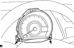
REMOVE COMBINATION METER ASSEMBLY
-
Remove the 2 bolts.
-
Disconnect the 14 connectors and remove the combination meter.
-
-
REMOVE COMBINATION SWITCH ASSEMBLY
-
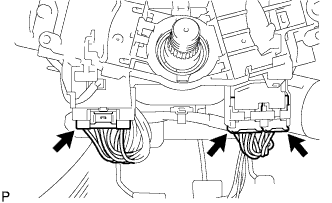
Disconnect the 3 connectors.
-
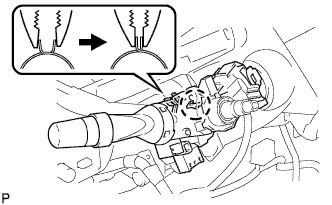
Remove the combination switch assembly, as shown in the illustration.
-
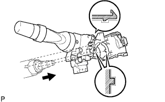
Disengage the 2 claws and remove the combination switch assembly.
-
-
REMOVE FRONT DOOR OPENING TRIM WEATHERSTRIP LH
-
Separate the front door opening trim weatherstrip LH.
-
-
REMOVE FRONT DOOR OPENING TRIM WEATHERSTRIP RH
-
REMOVE FRONT PILLAR GARNISH LH (w/ Curtain Shield Airbag)
Tech Tips
Use the same procedure as for the RH side.
-
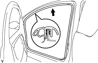
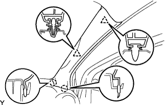
REMOVE FRONT PILLAR GARNISH RH (w/ Curtain Shield Airbag)
-
Disengage the 2 clips and 2 claws, and remove the front pillar garnish.
-
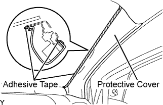
Completly cover the airbag with a piece of cloth or nylon of 700 mm (27.56 in.) x 120 mm (4.72 in.) and fix the ends of the cover with adhesive tape, as shown in the illustration.
Note
Cover the curtain shield airbag with the protective cover as soon as the front pillar garnish is removed.
-
-
REMOVE FRONT PILLAR GARNISH LH (w/o Curtain Shield Airbag)
Tech Tips
Use the same procedure as for the RH side.
-
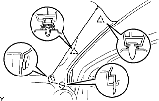
REMOVE FRONT PILLAR GARNISH RH (w/o Curtain Shield Airbag)
-
Disengage the 2 clips and 2 claws, and remove the front pillar garnish.
-
-
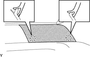
REMOVE INSTRUMENT PANEL SPEAKER PANEL SUB-ASSEMBLY NO. 2
-
Disengage the 2 claws.
-
-
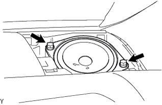
REMOVE FRONT NO. 1 SPEAKER ASSEMBLY
-
Remove the 2 screws.
-
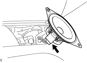
Disconnect the connector.
-
-
REMOVE INSTRUMENT PANEL SPEAKER PANEL SUB-ASSEMBLY NO. 1
-
REMOVE FRONT NO. 1 SPEAKER ASSEMBLY
-
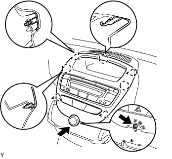
REMOVE INSTRUMENT CLUSTER FINISH PANEL SUB-ASSEMBLY CENTER
-
Remove the control knob.
-
Remove the screw.
-
Disengage the 4 clips and 3 claws and remove the cluster finish panel by pulling it up from underneath.
-
Disconnect the connectors and remove the instrument cluster finish panel center.
-
-
REMOVE INSTRUMENT PANEL ASSEMBLY
-
Disengage the 2 claws and open the cover.
-
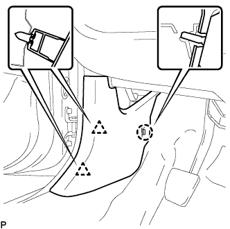
Disconnect the airbag connector, as shown in the illustration.
-
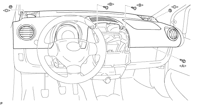
Remove the bolt <A>, 2 nuts <D> and 2 screws <B>.
-
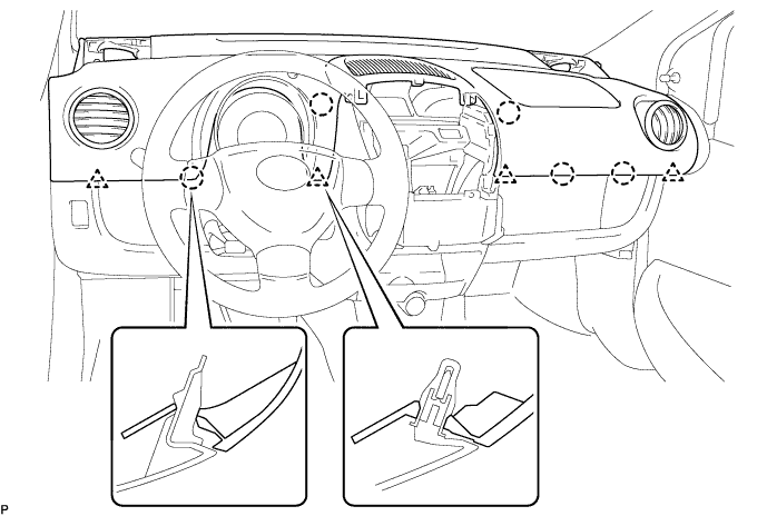
Disengage the 4 clips and 5 claws and remove the instrument panel assembly.
-
-
REMOVE COWL SIDE TRIM BOARD LH
-
Disengage the 2 clips and claw, and remove the cowl side trim board LH.
-
-
REMOVE COWL SIDE TRIM BOARD RH
-
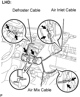
REMOVE HEATER CONTROL ASSEMBLY (for LHD)
Note
Do not bend the cable when removing the heater control assembly.
-
Separate the black air mix cable from the clamp and remove the cable ring from the temperature control link.
-
Separate the white air inlet cable from the clamp and remove the cable ring from the air inlet control link.
-
Separate the blue defroster cable from the clamp and remove it from the mode link.
-
Remove the 2 screws, disengage the 2 claws and remove the heater control assembly.
-
-
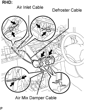
REMOVE HEATER CONTROL ASSEMBLY (for RHD)
Note
Do not bend the cable when removing the heater control assembly.
-
Separate the black air mix cable from the clamp and remove the cable ring from the temperature control link.
-
Separate the white air inlet cable from the clamp and remove the cable ring from the air inlet control link.
-
Separate the blue defroster cable from the clamp and remove it from the mode link.
-
Remove the 2 screws, disengage the 2 claws and remove the heater control assembly.
-
-
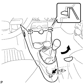
REMOVE CONSOLE BOX
-
Remove the shift knob.
-
Remove the box bottom mat.
-
Remove the bolt <E>.
-
Disengage the 2 claws and remove the console box.
-
-
REMOVE INSTRUMENT PANEL ASSEMBLY LOWER
-
Disengage the 2 claws and open the cover.
-
Disconnect the airbag connector, as shown in the illustration.
-
Remove the bolt <A>, 2 nuts <D> and 2 screws <B>.
-
Disengage the 4 clips and 5 claws and remove the instrument panel assembly.
-
-
REMOVE STEERING COLUMN HOLE COVER PLATE
-
Turn back the floor carpet and disengage the 2 claws from the steering hole cover plate.
-
-
REMOVE STEERING COLUMN PROTECTOR NO. 1 (RHD-E/PS-MT)
-
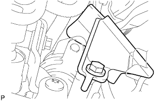
Remove the bolt and steering column protector No. 1 from the power steering motor assembly.
-
-
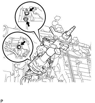
SEPARATE STEERING INTERMEDIATE SHAFT ASSEMBLY NO. 2
-
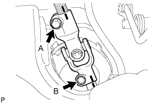
Loosen bolt A.
-
Put matchmarks, as shown in the illustration.
-
Remove bolt B and separate the steering intermediate shaft assembly No. 2 from the steering gear assembly.
-
-
REMOVE STEERING COLUMN ASSEMBLY
-
Disconnect the 2 connectors.
-
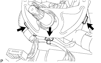
Disengage the 3 clamps and disconnect the wire harness.
-
Remove the 3 bolts and steering column assembly.
-
-
REMOVE INSTRUMENT PANEL BRACE SUB-ASSEMBLY NO. 1

-
Remove the clip and fold back the floor carpet.
-
Disengage the 2 clamps.
-
Remove the 2 wire harness clamp bolts.
-
Remove the bolt, screw, nut and instrument panel brace sub-assembly No. 1.
-
-
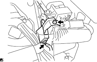
REMOVE TRANSPONDER KEY ECU ASSEMBLY
-
Remove the bolt.
-
Disconnect the connector and remove the transponder key ECU assembly.
-
-
REMOVE DOOR CONTROL WITH RECEIVER ECU ASSEMBLY

-
Disconnect the connector.
-
Remove the bolt and door control with receiver ECU assembly.
-
-
SEPARATE CONNECTOR HOLDER

-
Remove the screw and separate the connector holder.
-
-
SEPARATE RELAY BLOCK ASSEMBLY

-
Remove the screw.
-
Disengage the clamp and separate the relay block assembly.
-
-
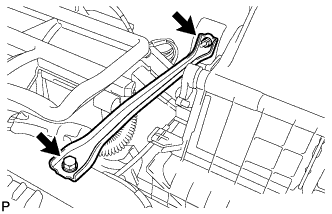
REMOVE INSTRUMENT PANEL TO COWL BRACE CENTER
-
Remove the bolt, nut and instrument panel to cowl brace center.
-
-
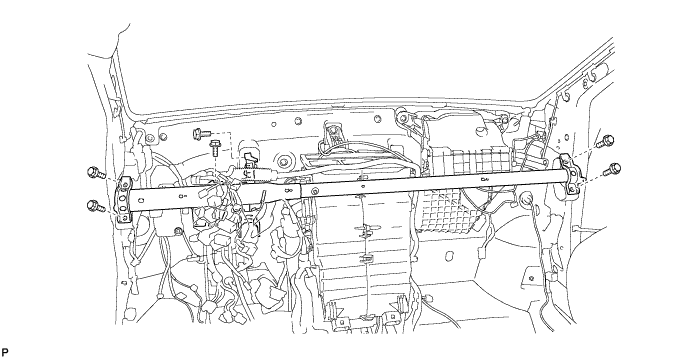
REMOVE INSTRUMENT PANEL REINFORCEMENT
-
Disengage the 7 clamps.
-
Remove the bolt.

-
Remove the 6 bolts and instrument panel reinforcement.
-
-
REMOVE AIR CONDITIONER UNIT ASSEMBLY
-
Disconnect the 3 connectors and 2 clamps.

-

Disengage the connector lever and separate the PTC heater connector. (for Cold Area Specification Vehicles)
-
Remove the clip, 5 nuts and air conditioner unit sub-assembly.

-