AIR CONDITIONING UNIT (for 1KR-FE) INSTALLATION

-
INSTALL AIR CONDITIONER UNIT ASSEMBLY
Tech Tips
If a new air conditioner unit assembly is installed, add compressor oil to the evaporator as follows.
Compressor oil ZXL 200PG or equivalent Add 30 cc (1.06 fl.oz.)
-
Install the air conditioner unit assembly with the clip and 5 nuts.
- Torque:
- 9.8 N*m { 100 kgf*cm, 87 in.*lbf }
-
Connect the 3 connectors and clamp.
-
-
INSTALL INSTRUMENT PANEL REINFORCEMENT
-
Install the instrument panel reinforcement with the 6 bolts.
- Torque:
- 29 N*m { 300 kgf*cm, 21 ft.*lbf }
-
Install the screw.
Note
Replace the screw with 90168-W0001 screws to avoid insecure installation.
-
Engage the 7 clamps.
-
-
INSTALL RELAY BLOCK ASSEMBLY
-
Engage the clamp.
-
Install the relay block assembly with the screw.
- Torque:
- 3.7 N*m { 38 kgf*cm, 32 in.*lbf }
Note
Replace the screw with 90168-W0001 screws to avoid insecure installation.
-
-
INSTALL CONNECTOR HOLDER
-
Install the connector holder with the screw.
- Torque:
- 3.7 N*m { 38 kgf*cm, 32 in.*lbf }
-
-
INSTALL DOOR CONTROL WITH RECEIVER ECU ASSEMBLY
-
Install the door control with receiver ECU assembly with the bolt.
- Torque:
- 3.7 N*m { 38 kgf*cm, 32 in.*lbf }
-
Connect the connector.
-
-
INSTALL TRANSPONDER KEY ECU ASSEMBLY
-
Connect the connector.
-
Install the transponder key ECU assembly with the bolt.
- Torque:
- 3.7 N*m { 38 kgf*cm, 32 in.*lbf }
-
-
INSTALL AIR DUCT REAR NO. 1 (for Cold Area Specification Vehicles)
-
Engage the 2 claws and install the air duct rear No. 1.
-
Put the floor carpet back down.
-
-
INSTALL AIR DUCT REAR NO. 2 (for Cold Area Specification Vehicles)
-
Engage the 2 claws and install the air duct rear No. 2.
-
Put the floor carpet back down.
-
-
INSTALL INSTRUMENT PANEL BRACE SUB-ASSEMBLY NO. 1
-
Install the instrument panel brace sub-assembly No. 1 with the bolt, nut and screw.
- Torque:
- 29 N*m { 300 kgf*cm, 21 ft.*lbf, for bolt }
- 29 N*m { 300 kgf*cm, 21 ft.*lbf, for nut }
- 1.2 N*m { 12 kgf*cm, 11 in.*lbf, for screw }
-
Install the 2 wire harness clamp bolts.
-
Engage the 2 clamps.
-
Install the floor carpet with the clip.
-
-
INSTALL STEERING COLUMN ASSEMBLY
-
INSTALL HEATER WATER OUTLET HOSE
-
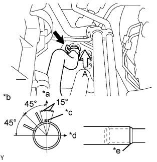
Text in Illustration *a UP *b View A *c Blue Paint Mark *d LH *e Spool Install the heater water outlet hose onto the heater unit.
Note
Perform the installation with the hose clip and mark at the correct angle.
-
-
INSTALL HEATER WATER INLET HOSE
-
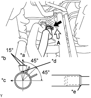
Text in Illustration *a UP *b View A *c RH *d Pink Paint Mark *e Spool Install the heater water inlet hose onto the heater unit.
Note
Perform the installation with the hose clip and mark at the correct angle.
-
-
INSTALL SUCTION HOSE SUB-ASSEMBLY
-
Apply compressor oil to 2 new O-rings and install them onto the tube.
Compressor oil ZXL 200PG or equivalent -
Install the suction hose and air conditioning tube with the bolt.
- Torque:
- 9.8 N*m { 100 kgf*cm, 87 in.*lbf }
-
-
ADD ENGINE COOLANT
-
Connect the engine side radiator outlet hose .
-
Install the cylinder block drain cock plug.
- Torque:
- 20 N*m { 204 kgf*cm, 15 ft.*lbf }
-
Pour engine coolant into the radiator assembly until it is full.
Capacity Specification Capacity except Tropic Spec 4.0 liters (4.2 US qts, 3.5 Imp qts) for Tropic Spec 4.4 liters (4.6 US qts, 3.9 Imp qts) Note
Do not substitute water for engine coolant.
Tech Tips
-
Use of improper engine coolant may damage the engine cooling system.
-
Use only Toyota Super Long Life Coolant or similar high quality ethylene glycol based non-silicate, non-amine, non-nitrite, and non-borate engine coolant with long-life hybrid organic acid technology (coolant with long-life hybrid organic acid technology consists of a combination of low phosphates and organic acids).
-
-
Check the engine coolant level inside the radiator assembly by pressing the inlet and outlet radiator hoses several times by hand. If the engine coolant level goes down, add engine coolant.
-
Install the radiator cap sub-assembly securely.
-
Slowly pour engine coolant into the radiator reservoir until it reaches the FULL line.
-
Bleed air from the cooling system.
-
Warm up the engine until the thermostat opens.
While the thermostat is open, circulate the coolant for several minutes.
-
The thermostat open timing can be confirmed by pressing the outlet radiator hose by hand, and checking when the coolant starts to flow inside the hose.
-
Maintain the engine speed at 2500 to 3000 rpm and warm up the engine until the cooling fan operates.
-
Press the outlet radiator hose and inlet radiator hose several times by hand to bleed air.
CAUTION:
When pressing the radiator hoses:
-
Wear protective gloves.
-
Be careful as the radiator hoses are hot.
-
Keep your hands away from the radiator fan.
-
-
-
Stop the engine and wait until the coolant cools down.
-
If the engine coolant level is below the full level, perform steps (c) through (h) and repeat the operation until the engine coolant level stays the full level.
-
Recheck the engine coolant level inside the radiator reservoir tank assembly. If it is below the full level, add engine coolant.
-
-
CHARGE REFRIGERANT
- SST
- 07110-58060 ( 07117-58080, 07117-58090, 07117-78050, 07117-88060, 07117-88070, 07117-88080 )
Note
Be sure to charge refrigerant in accordance with equipment manual.
-
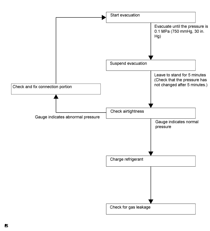
Perform vacuum purging using a vacuum pump.
-
Charge refrigerant HFC-134a (R134a).
Standard 420 to 480g (14.81 to 16.93oz.) for IKR-FE 470 to 530g (16.58 to 18.69oz.) for 2WZ-TV Note
Do not start the engine before charging it with refrigerant as the cooler compressor doesn't work properly without sufficient refrigerant. This could cause the compressor to overheat.
Tech Tips
-
The relationship between refrigerant charge amount and pressure is as follows.
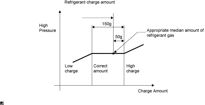
-
Correct charging amount is approximately 450g.
-
High Charge Range:
If refrigerant is overcharged, pressure rises on the high-pressure side. High-pressure cut off frequently occurs. This causes insufficient cooling performance and also insufficient compressor lubrication.
-
Low Charge Range:
Shortage of refrigerant causes insufficient cooling performance and low circulation of refrigerant oil, which shortens compressor life. Operation with insufficient coolant raises refrigerant temperature and causes heat deterioration of rubber seals and hoses. Cracking and thus refrigerant leakage may occur.
-
Install the caps onto the service valves on the refrigerant line.
-
-
INSPECT FOR ENGINE COOLANT LEAKS
CAUTION:
To avoid the danger of being burned, do not remove the radiator cap sub-assembly while the engine and radiator assembly are still hot. Thermal expansion will cause hot engine coolant and steam to blow out from the radiator assembly.
-
Fill the radiator assembly with engine coolant, then attach a radiator cap tester.
-
Warm up the engine.
-
Pump it to 137 kpa (1.4 kgf*cm2, 19.9 psi), then check that the pressure does not drop.
-
If the pressure drops, check the hoses, radiator assembly and water pump assembly for leaks. If there are no signs or traces of external engine coolant leaks, check the heater core, cylinder block and head.
-
-
Be sure not to put more than 177 kpa (1.8 kgf*cm2, 25.6 psi).
-
-
WARM UP ENGINE
Note
Warm up the engine at less than 2,000 rpm for 1 minute or more after charging it with refrigerant.
-
INSPECT FOR REFRIGERANT LEAKS
-
After recharging the refrigerant gas, check for refrigerant gas leakage using a halogen leak detector.
-
Perform the operation as follows:
-
Stop the engine.
-
Secure good ventilation (the gas leak detector may react to volatile gases other than refrigerant, such as evaporated gasoline or exhaust gas).
-
Repeat the test 2 or 3 times.
-
Make sure that some refrigerant remains in the refrigeration system.
When compressor is off: approximately 392 to 588 kPa (4 to 6 kgf*cm2, 57 to 85 psi)
Tech Tips
It is impossible for the above pressure to be maintained if there is leakage.
-
-
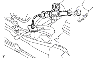
Using a gas leak detector, check the refrigerant line, especially the connecting points, for leakage.
-
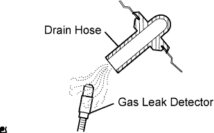
Bring the gas leak detector close to the drain hose before performing the test.
Tech Tips
-
After the blower motor has stopped, leave the cooling unit for at least 15 minutes.
-
Place the gas leak detector sensor under the drain hose.
-
When bringing the gas leak detector close to the drain hose, make sure that the gas leak detector does not react to the volatile gases.
If such a reaction is unavoidable, the vehicle must be lifted up.
-
-
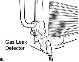
If a gas leak is not detected from the drain hose, remove the blower motor from the cooling unit. Insert the gas leak detector sensor into the unit and perform the test.
-
Disconnect the pressure switch connector and leave it for approximately 20 minutes. Bring the gas leak detector close to the pressure switch and perform the test.
-