AIR CONDITIONING SYSTEM (for 2WZ-TV) TERMINALS OF ECU

-
AIR CONDITIONER AMPLIFIER ASSEMBLY
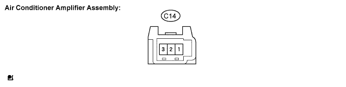
Terminal No. (Symbols) Wiring Color Terminal Description Condition Specification C14-1 (PRS) - C14-2 (E) Y - W-B A/C switch signal While engine idling
Blower switch: LO
A/C switch: OFF to ON
Below 1 V →10 to 14 V C14-3 (AC1) - C14-2 (E) B - W-B A/C magnetic clutch signal Ignition switch: ON
Magnet clutch: OFF to ON
10 to 14 V →Below 1 V C14-2 (E) - Body ground W-B - Body ground Ground for main power supply Always Below 1 Ω -
ECM
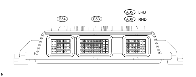
Terminal No. (Symbols) Wiring Color Terminal Description Condition Specification B54-24 (MGC) - B54-12 (E2) - Magnetic clutch relay signal While engine idling
Blower switch: LO
A/C switch: OFF to ON
Below 1 V →10 to 14 V B53-1 (AC1) - B53-38 (E1) - A/C amplifier signal While engine idling
Blower switch: LO
A/C switch: OFF to ON
Below 1 V →10 to 14 V B53-38 (E1) - Body ground - - Body ground Ground for power supply Always Below 1 Ω B54-12 (E2) - Body ground - - Body ground Ground for power supply Always Below 1 Ω A35-30 (PDIN)*1 - A35-24 (GND)*1
A36-30 (PDIN)*2 - A36-24 (GND)*2
L - P Pressure sensor signal While engine idling
Blower switch: LO
A/C switch: OFF to ON.
Refrigerant pressure in normal operating range: 0.176 MPa (1.8 kgf/ cm2. 26 psi) to 3.025 MPa (30.9 kgf/ cm2. 439psi)*3
Below 1 V →0.76 to 4.74 V A35-22 (5V)*1 - A35-24 (GND)*1
A36-22 (5V)*2 - A36-24 (GND)*2
G - P Pressure sensor signal Ignition switch: ON 4.5 to 5.5 V *1: LHD
*2: RHD
*3: If refrigerant pressure is outside the normal operating range, the pressure switch signal stays below 1V even when the A/C switch is ON.
Tech Tips
If the outside air temperature is low, the conditions which are required to activate the compressor may not be satisfied.