POWER STEERING GEAR INSTALLATION

-
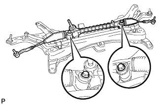
INSTALL STEERING GEAR ASSEMBLY
-
Install the 2 bolts, 2 nuts and steering gear assembly onto the suspension crossmember sub-assembly.
- Torque:
- 89 N*m { 902 kgf*cm, 65 ft.*lbf }
-
Install the steering column hole cover onto the steering gear assembly.
Note
Install the steering column hole cover securely.
-
-
INSTALL FRONT SUSPENSION CROSSMEMBER SUB-ASSEMBLY
-
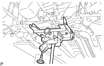
Using a transmission jack, support the front suspension crossmember sub-assembly.
-
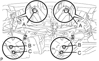
Install the 6 bolts and the front suspension crossmember sub-assembly.
- Torque:
- 85 N*m { 867 kgf*cm, 63 ft.*lbf, for bolt A }
- 128 N*m { 1,305 kgf*cm, 95 ft.*lbf, for bolt B }
- 48 N*m { 489 kgf*cm, 35 ft.*lbf, for bolt C }
-
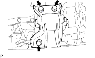
Install the 3 bolts onto the engine mounting control bracket (for 1KR-FE).
- Torque:
- 52 N*m { 530 kgf*cm, 38 ft.*lbf }
-
Install the control rod onto the engine mounting control bracket with the bolt (2WZ-TV).
- Torque:
- 120 N*m { 1,224 kgf*cm, 89 ft.*lbf }
-
Remove the engine sling device.
-
Remove the No. 1 and No. 2 engine hangers (for 1KR-FE).
-
-
INSTALL EXHAUST PIPE ASSEMBLY FRONT (for 1KR-FE)
-
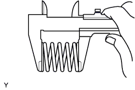
Using vernier calipers, measure the free length of the compression spring.
Minimum length 40.5 mm (1.594 in.)
-
If the length is not as specified, replace the compression spring.
-
-
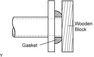
Using a plastic hammer and a wooden block, tap in a new exhaust pipe gasket until its surface is flush with the exhaust manifold.
Note
-
Be sure to install the exhaust pipe gasket in the correct direction.
-
Do not damage the outer surface of the exhaust pipe gasket.
-
Do not reuse the exhaust pipe gasket.
-
Do not push in the gasket with the exhaust pipe when connecting it.
-
-
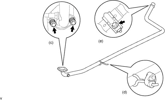
Install the exhaust front pipe assembly and a new exhaust pipe gasket with the 2 compression springs and 2 bolts.
- Torque:
- 45 N*m { 459 kgf*cm, 33 ft.*lbf }
-
Install the exhaust pipe No.4 support.
-
Install the bolt and clamp.
- Torque:
- 32 N*m { 326 kgf*cm, 24 ft.*lbf }
Note
-
Clamp marks and stamping should be aligned.
-
-
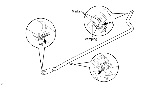
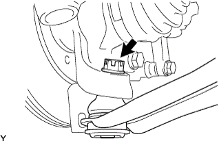
INSTALL EXHAUST PIPE ASSEMBLY FRONT (for 2WZ-TV)
-
Install the exhaust front pipe assembly with a new clamp.
- Torque:
- 25 N*m { 255 kgf*cm, 18 ft.*lbf }
-
Install the exhaust front pipe stay nut and exhaust pipe support No.4.
- Torque:
- 7.7 N*m { 79 kgf*cm, 68 ft.*lbf }
-
Install a new clamp and bolt.
- Torque:
- 32 N*m { 326 kgf*cm, 24 ft.*lbf }
Note
The clamp marks and stampings should be aligned.
-
-
INSTALL OXYGEN SENSOR (for 1KR-FE)
-
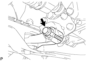
Using SST, install the oxygen sensor.
- SST
- 09224-00010
- Torque:
- 44 N*m { 449 kgf*cm, 32 ft.*lbf }
-
Connect the oxygen sensor connector.
-
-
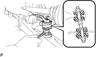
INSTALL FRONT SUSPENSION ARM SUB-ASSEMBLY LOWER NO. 1 LH
-
Push the front suspension lower arm No. 1 downward, install the front lower ball joint and tighten the castle nut and a new clip.
- Torque:
- 98 N*m { 1,000 kgf*cm, 72 ft.*lbf }
Note
Retighten the castle nut and clip within a turning angle of 60° after aligning the hole of the clip with the castle nut.
-
-
INSTALL FRONT SUSPENSION ARM SUB-ASSEMBLY LOWER NO. 1 RH
Tech Tips
Perform the same procedure as for the LH side.
-
INSTALL FRONT STABILIZER BAR
-
Install the stabilizer bar front with the 2 cushion retainers, 2 cushions and a nut, as shown in the illustration.
Note
Be sure to install the cushion and retainer in the correct direction.
-
Tighten the nut with a spanner (10 mm).
- Torque:
- 18 N*m { 184 kgf*cm, 13 ft.*lbf }
-
-
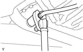
INSTALL TIE ROD END SUB-ASSEMBLY LH
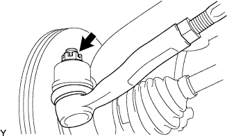
-
Connect the tie rod end to the steering knuckle and install it with the castle nut and a new cotter pin.
- Torque:
- 33 N*m { 336 kgf*cm, 24 ft.*lbf }
Note
Retighten the castle nut and cotter pin within a turning angle of 60° after aligning the hole of the cotter pin with the castle nut.
-
-
INSTALL TIE ROD END SUB-ASSEMBLY RH
Tech Tips
Perform the same procedure as for the LH side.
-
INSTALL STEERING COLUMN HOLE COVER SUB-ASSEMBLY NO.1
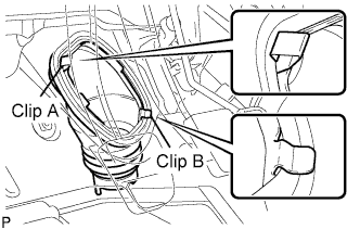
-
Install clip B onto the vehicle body and install the steering column hole cover onto the vehicle body with clip A.
Note
Fit the lip of the steering column hole cover correctly onto the dash panel.
-
-
INSTALL STEERING INTERMEDIATE SHAFT ASSEMBLY NO. 2
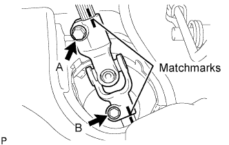
-
Align the matchmarks and install steering intermediate shaft assembly No. 2 onto the steering gear sub-assembly with bolt B.
- Torque:
- 35 N*m { 360 kgf*cm, 26 ft.*lbf }
-
Tighten bolt A.
- Torque:
- 35 N*m { 360 kgf*cm, 26 ft.*lbf }
-
Release the seat belt from the steering wheel.
-
-
INSTALL STEERING COLUMN HOLE COVER PLATE
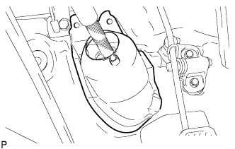
-
Engage the steering hole plate.
-
-
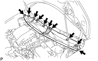
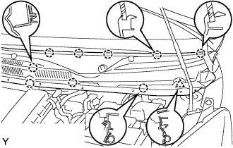
INSTALL COWL TOP PANEL OUTER
-
Install the cowl top panel with the 10 bolts.
- Torque:
- 9.2 N*m { 94 kgf*cm, 81 in.*lbf }
-
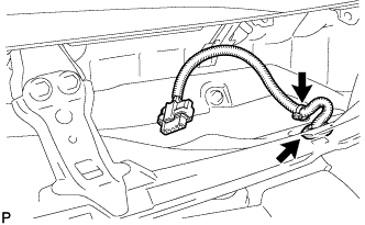
Install the grommet of the wire harness.
-
Install the clamp of the wire harness.
-
-
INSTALL FRONT WIPER MOTOR AND LINK ASSEMBLY
-
Connect the connector.
-
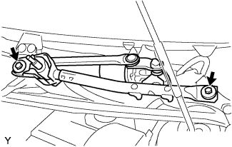
Install the front wiper motor and link assembly with the 2 bolts.
- Torque:
- 13 N*m { 127 kgf*cm, 9 ft.*lbf }
-
-
INSTALL COWL TOP VENTILATOR LOUVER RH
-
Connect the washer hose.
-

Engage the 8 claws and install the cowl top ventilator louver RH.
-
Install the clip.
-
-
INSTALL COWL TOP VENTILATOR LOUVER LH
-
Connect the washer hose.
-
Engage the 9 claws and install the cowl top ventilator louver LH.
-
Install the clip.
-
-
INSTALL HOOD TO COWL TOP SEAL

-
Engage the 8 clips and install the hood to cowl top seal.
-
-
INSTALL FRONT WIPER ARM LH
-
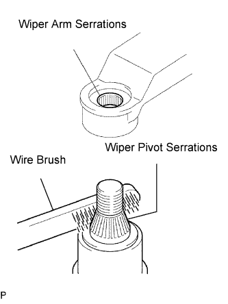
Scrape any metal powder off the serrated part of the wiper arm with a round file or equivalent (when reinstalling).
-
Clean the wiper pivot serrations with a wire brush.
-
Operate the wiper, then stop the windshield wiper motor assembly in the automatic stop position.
-
Provisionally install the front wiper main arm with the nut.
-
Install the front wiper secondary arm onto the front wiper motor and link assembly.
-
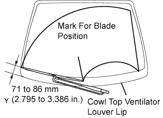
Align the blade tip with the mark on the windshield glass, as shown in the illustration.
-
Tighten the nut of the front wiper main arm.
- Torque:
- 21 N*m { 209 kgf*cm, 15 ft.*lbf }
-
-
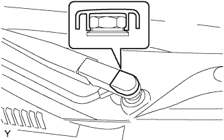
INSTALL FRONT WIPER ARM HEAD CAP
-
Engage the claw and install the front wiper arm head cap.
-
-
INSTALL AIR HOSE (for 2WZ-TV)
-
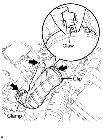
Install the air hose with the clamp and a new clip.
- Torque:
- Clamp
- 5.0 N*m { 51 kgf*cm, 44 in.*lbf }
-
-
REMOVE ENGINE COVER (for 2WZ-TV)
-
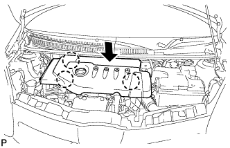
Align the 3 claws to install the engine cover.
-
-
CONNECT CABLE TO NEGATIVE BATTERY TERMINAL
- Torque:
- 5.4 N*m { 55 kgf*cm, 48 in.*lbf }
-
INSTALL FRONT WHEEL
- Torque:
- 103 N*m { 1,050 kgf*cm, 76 ft.*lbf }
-
CHECK FOR EXHAUST GAS LEAKAGE
-
INSPECT FRONT WHEEL ALIGNMENT