ELECTRONIC POWER STEERING SYSTEM TS and CG Terminal Circuit
DESCRIPTION
After a short circuit is made between terminals TS and CG of the DLC3 by turning the ignition switch OFF, the mode changes from normal mode when the ignition switch is turned ON. After the ignition switch is turned ON, there a DTC is output from TC terminal of the DLC3.
WIRING DIAGRAM
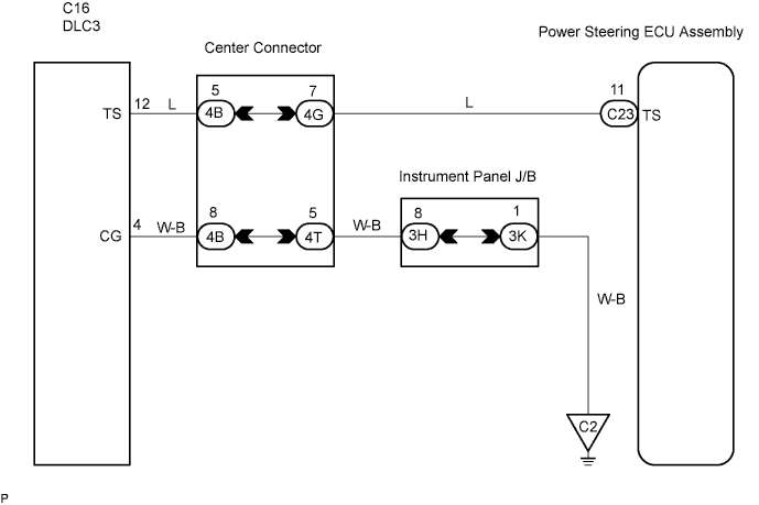
INSPECTION PROCEDURE
PROCEDURE
-
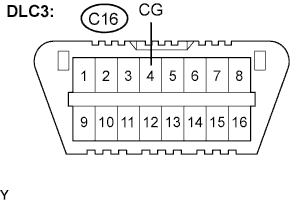
INSPECT DLC3 TERMINAL VOLTAGE (TS TERMINAL TS-CG)
-
Turn ignition switch ON.
-
Measure the voltage.
Standard Voltage Tester Connection Specified Condition C16-12 (TS) - C16-4 (CG) 10 to 14 V
OK 
CHECK HARNESS AND CONNECTOR (POWER STEERING ECU ASSEMBLY - DLC3) Click here
NG 
-
-
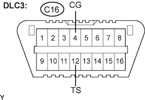
CHECK HARNESS AND CONNECTOR (DLC3 - BODY GROUND)
-
Measure the resistance.
Standard Resistance Tester Connection Specified Condition C16-4 (CG) - Body ground Below 1 Ω
NG 
REPAIR OR REPLACE HARNESS OR CONNECTOR
OK
-
-
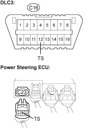
CHECK HARNESS AND CONNECTOR (POWER STEERING ECU ASSEMBLY - DLC3)
-
Disconnect the power steering ECU connector C23.
-
Measure the resistance.
Standard Resistance Tester Connection Specified Condition C23-11 (TS) - C16-12 (TS) Below 1 Ω C23-11 (TS) - Body ground 10 kΩ or higher -
Reconnect the connector.
NG
REPAIR OR REPLACE HARNESS OR CONNECTOR
OK 
REPLACE POWER STEERING ECU ASSEMBLY
-