ELECTRONIC POWER STEERING SYSTEM EPS Warning Light Circuit
DESCRIPTION
If the power steering ECU assembly detects a malfunction, the P/S warning light illuminates. At this time, the power steering ECU assembly records a DTC in its memory.
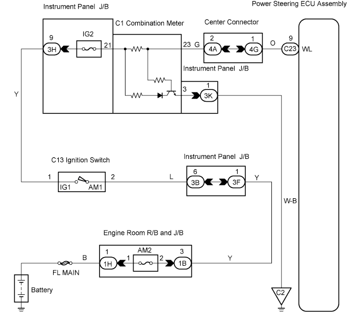
WIRING DIAGRAM
INSPECTION PROCEDURE
PROCEDURE
-
CHECK HARNESS AND CONNECTOR (POWER STEERING ECU ASSEMBLY - COMBINATION METER ASSEMBLY)
-
Check the indication of the PS warning while by wiggling the power steering ECU assembly connector and wire harness up and down, and right and left.
OK PS warning indication does not change.
NG 
REPAIR OR REPLACE HARNESS OR CONNECTOR
OK 
-
-
CHECK HARNESS AND CONNECTOR (POWER STEERING ECU ASSEMBLY - BODY GROUND)
-
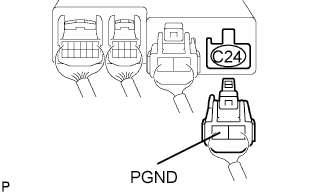
Disconnect the C24 connector from the power steering ECU assembly.
-
Check the resistance between terminal PGND of the C24 connector and body ground.
Standard Resistance Below 1 Ω or more -
Reconnect the connector.
NG
REPAIR OR REPLACE HARNESS OR CONNECTOR
OK
-
-
INSPECT POWER STEERING ECU ASSEMBLY
-
Turn the ignition switch ON.
-
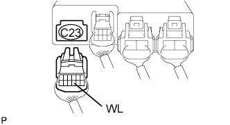
Disconnect the C23 connector from the power steering ECU assembly, and check the P/S warning light goes OFF.
OK P/S warning light comes on and then goes off -
Reconnect the connector.
NG
REPLACE POWER STEERING ECU ASSEMBLY
OK 
GO TO COMBINATION METER SYSTEM
-