ELECTRONIC POWER STEERING SYSTEM, Diagnostic DTC:C1551/51

| DTC Code | DTC Name |
|---|---|
| C1551/51 | IG Power Source Circuit Malfunction |
DESCRIPTION
| DTC No. | DTC Detecting Condition | Trouble Areas |
|---|---|---|
| C1551/51 | Unusual IG voltage value which not within specified range input to power steering ECU assembly. |
|
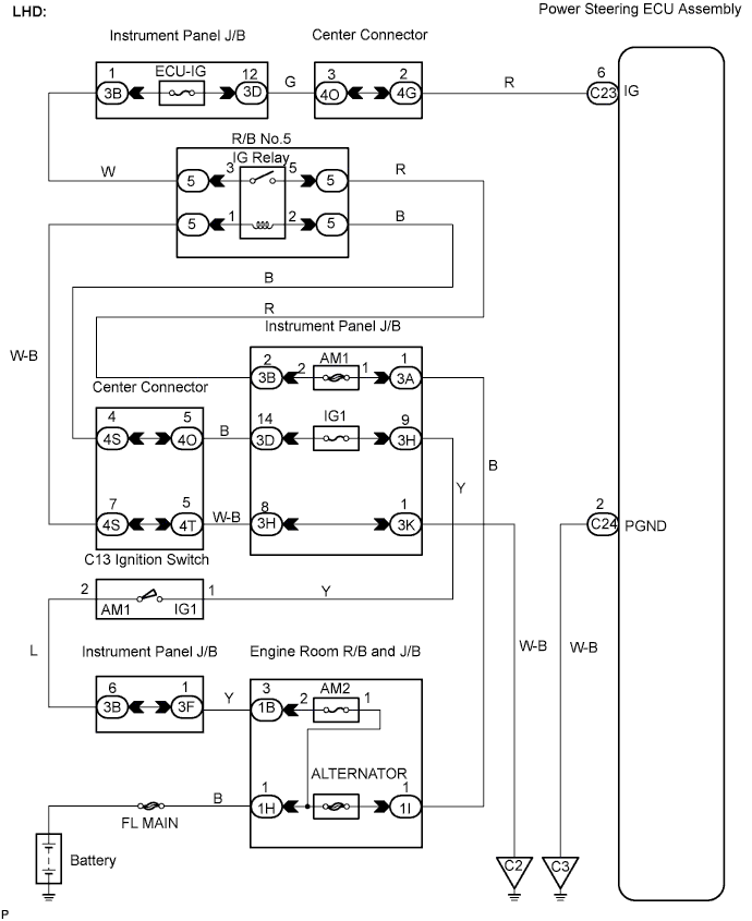
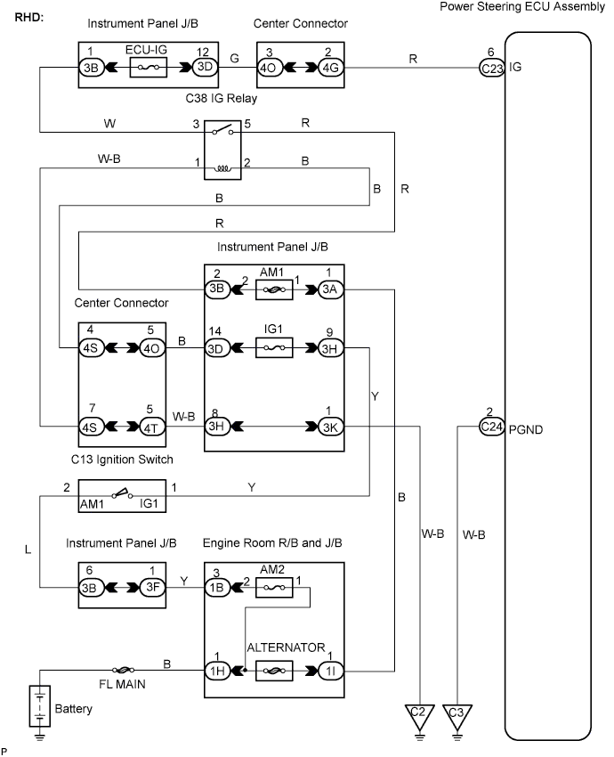
WIRING DIAGRAM
INSPECTION PROCEDURE
PROCEDURE
-
READ VALUE USING INTELLIGENT TESTER
-
Connect the intelligent tester to the DLC3.
-
Turn the ignition switch ON and turn the intelligent tester main switch ON.
-
Select the item PIG POWER SUPPLY in the DATA LIST and read the value displayed on the intelligent tester.
Standard Voltage 10 to 16 V
OK 
CHECK FOR INTERMITTENT PROBLEMS
NG 
-
-
INSPECT FUSE (ECU-IG)
-
Remove the ECU-IG fuse from the instrument panel J/B.
-
Check the resistance of the ECU-IG fuse.
Standard Resistance Below 1 Ω -
Reinstall the ECU-IG fuse.
NG
INSPECT FOR SHORT CIRUCUITS IN ALL HANESSES AND COMPONENTS CONNECTED TO ECU - IG FUSE
OK
-
-
CHECK HARNESS AND CONNECTOR (POWER STEERING ECU ASSEMBLY-BODY GROUND)
-
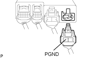
Disconnect the C24 connector from the power steering ECU assembly.
-
Measure the resistance between terminal PGND of C24 connector and body ground.
Standard Resistance 1 Ω or less -
Reconnect the connector.
NG
REPAIR OR REPLACE HARNESS OR CONNECTOR
OK
-
-
CHECK HARNESS AND CONNECTOR (POWER STEERING ECU ASSEMBLY - DRIVER SIDE J/B)
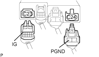
-
Disconnect the C23 and C24 connectors from the power steering ECU assembly.
-
Turn the ignition switch ON.
-
Measure the voltage between terminals IG and PGND of the C23 and C24 connectors.
Standard Voltage 10 to 16 V -
Reconnect the connectors.
NG
REPAIR OR REPLACE HARNESS OR CONNECTOR
OK 
REPLACE POWER STEERING ECU ASSEMBLY
-