ELECTRONIC POWER STEERING SYSTEM, Diagnostic DTC:C1541/41, C1542/42, C1571/71

| DTC Code | DTC Name |
|---|---|
| C1541/41 | Speed Sensor Malfunction |
| C1542/42 | Speed Sensor Malfunction |
| C1571/71 | Speed Sensor Malfunction (Test Mode DTC) |
DESCRIPTION
Based on the vehicle speed signal received from the combination meter, the power steering ECU adjusts the amount of power assist according to vehicle speed. The power steering ECU monitors the speed signal input and stores a DTC if a malfunction is detected. While a malfunction exists in the vehicle speed signal, fail-safe operation maintains the amount of power assist at the level for a speed of 70 km/h (43 mph).
Note
Revving the engine while the vehicle is stopped may cause DTC C1541/41 or C1542/42 to be stored.
Tech Tips
-
If C1541/41 is stored while the vehicle is stopped, driving the vehicle for 5 minutes or more and then turning the ignition switch off will clear the DTC.
-
If C1542/42 is stored while the vehicle is stopped, driving the vehicle for 5 minutes or more will clear the DTC.
-
When the sensor is normal, a pulse signal (43 Hz at 37 mph [60 km/h]) that alternates between 0 V and 5 V is transmitted to the ECU.
| DTC No. | Detection Item | Trouble Area |
|---|---|---|
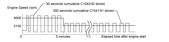
| C1541/41 | Vehicle Speed Signal Abnormal Increase |
|
| While vehicle stopped, engine rpm exceeds threshold* for 300 seconds or more, cumulative. | - | |
| C1542/42 | Vehicle Speed Signal Abnormal Decrease |
|
| While vehicle stopped, engine rpm exceeds threshold* for 30 seconds or more, cumulative. | - | |
| C1571/71 | Speed sensor malfunction (Test mode). |
|
*Threshold: An engine speed of 4000 rpm or greater is detected within 5 minutes after engine is started, or an engine speed of 2100 rpm or greater is detected 5 minutes or more after engine is started.
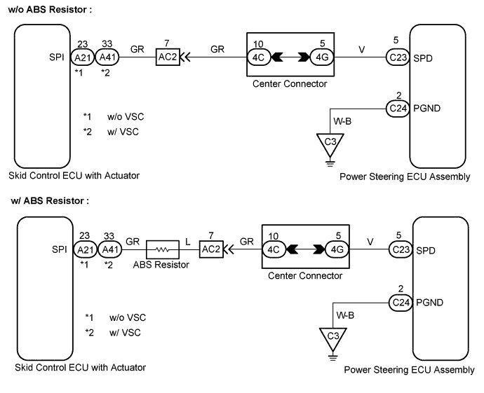
WIRING DIAGRAM
INSPECTION PROCEDURE
Tech Tips
-
Confirm that DTC C1571/71 has been cleared by activating test mode after the repair is completed.
PROCEDURE
-
CHECK DTC OUTPUT
Check whether the DTC for brake control system is output.
OK No DTC for brake control system is output.
NG 
REPAIR CIRCUIT INDICATED BY OUTPUT DTC
OK 
-
READ VALUE USING INTELLIGENT TESTER
-
Connect the intelligent tester to the DLC3.
-
Turn the ignition switch ON, and turn the intelligent tester main switch ON.
-
Select the item SPD in the DATA LIST and read the value displayed on the intelligent tester.
-
Check that there is no significant difference between the speed value output from the speedometer displayed by the intelligent tester and the speed value displayed by the speed meter when driving the vehicle.
OK Speed values are same. Tech Tips
There is tolerance of +-10% in the speed meter indication.
OK
REPLACE POWER STEERING ECU ASSEMBLY
NG
-
-
CHECK HARNESS AND CONNECTOR (POWER STEERING ECU ASSEMBLY - SKID CONTROL ECU)
-
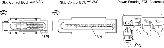
Disconnect the skid control ECU connector and power steering ECU connector C23.
-
Measure the resistance.
Standard resistance w/o VSC Tester Connection Specified Condition SPD (C23-5) - SP1 (A21-23) Below 1 Ω w/ ABS Resistor
SPD (C23-5) - SP1 (A21-23)
19 to 22 Ω SPD (C23-5) or SP1 (A21-23) - Body ground 10 kΩ or higher Standard resistance w/ VSC Tester Connection Specified Condition SPD (C23-5) - SP1 (A41-33) Below 1 Ω w/ ABS Resistor
SPD (C23-5) - SP1 (A41-33)
19 to 22 Ω SPD (C23-5) or SP1 (A41-33) - Body ground 10 kΩ or higher -
Reconnect the connector.
NG
REPAIR OR REPLACE HARNESS OR CONNECTOR
OK 
GO TO BRAKE CONTROL SYSTEM
-