ELECTRONIC POWER STEERING SYSTEM, Diagnostic DTC:C1511/11, C1512/12, C1513/13, C1514/14, C1517/17

| DTC Code | DTC Name |
|---|---|
| C1511/11 | Torque Sensor 1 Malfunction |
| C1512/12 | Torque Sensor Circuit Malfunction |
| C1513/13 | Torque Sensor Circuit Malfunction |
| C1514/14 | Torque Sensor Power Source Circuit Malfunction |
| C1517/17 | Torque Sensor Hold Malfunction |
DESCRIPTION
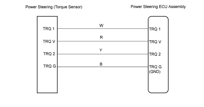
The torque sensor converts the power input from the steering wheel into electric signals, and sends it to the ECU.
| DTC No. | DTC Detecting Condition | Trouble Areas |
|---|---|---|
| C1511/11 | Torque sensor signal malfunctioning, or torque sensor circuit open |
|
| C1512/12 | ||
| C1513/13 | ||
| C1514/14 | Torque sensor power source voltage malfunction | |
| C1517/17 | Temporary control activated by torque sensor malfunction continues for long time |
WIRING DIAGRAM
INSPECTION PROCEDURE
PROCEDURE
-
READ VALUE USING INTELLIGENT TESTER
-
Connect the intelligent tester to the DLC3.
-
Turn the ignition switch ON and push the intelligent tester main switch ON.
-
Select the item TORQUE SENSOR 1 OUTPUT and TORQUE SENSOR 2 OUTPUT in the DATA LIST and read the value displayed on the intelligent tester.
-
Check the value on the torque sensor 1 output and torque sensor 2 output of the data monitor with the steering wheel in the center value position (no load).
Standard Voltage 2.3 to 2.7 V -
Check the difference in the values between torque sensor 1 output and torque sensor 2 output with the steering wheel in the center value position (no load)
Standard Voltage 0.3 V or less -
Check the values of the data monitor when turning the steering wheel.
(1) Turn the steering wheel to the right end from the center value position, and check the values on the torque sensor 1 output and torque sensor 2 output of the data monitor.
Standard Voltage 2.5 to 4.7 V (2) Turn the steering wheel to the left end from the center value position, and check the values on the torque sensor 1 output and torque sensor 2 output of the data monitor.
Standard Voltage 0.3 to 2.5 V (3) Check the difference in the values between torque sensor 1 output and torque sensor 2 output.
Standard Voltage 0.3 V or less OK All the check results shown above are within their standard ranges.
NG 
CHECK HARNESS AND CONNECTOR (POWER STEERING ECU - STEERING COLUMN ASSEMBLY(TORQUE SENSOR)) Click here
OK 
-
-
INSPECT POWER STEERING ECU ASSEMBLY
-
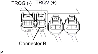
Measure the voltage between terminals torque sensor V and torque sensor G of the power steering ECU assembly connector.
Standard Voltage 7.5 to 8.5 V
NG
CHECK HARNESS AND CONNECTOR (POWER STEERING ECU - STEERING COLUMN ASSEMBLY(TORQUE SENSOR)) Click here
OK 
REPLACE POWER STEERING ECU ASSEMBLY
-
-
CHECK HARNESS AND CONNECTOR (POWER STEERING ECU - STEERING COLUMN ASSEMBLY(TORQUE SENSOR))
-
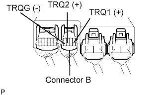
Measure the voltage.
Standard Voltage Condition TRQ 1 TRQ 2 Center position 2.3 to 2.7 V 2.3 to 2.7 V Turned right 2.5 to 4.7 V 2.5 to 4.7 V Turned left 0.3 to 2.5 V 0.3 to 2.5 V
NG 
REPLACE POWER STEERING ECU ASSEMBLY
OK
REPLACE STEERING COLUMN ASSEMBLY
-