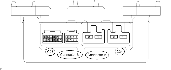
ELECTRONIC POWER STEERING SYSTEM TERMINALS OF ECU

| Symbols (Terminals No.) | Wiring Color | Terminal Description | Condition | Specified Condition |
|---|---|---|---|---|
| PIG (C24-1) - PGND (C24-2) | B - W-B | EMPS fuse | Always | 10 to 16 V |
| PGND (C24-2) - Body ground | W-B - Body ground | Body ground | Always | Below 1 Ω |
| M1 (A-1) - PGND (C24-2) | R - W-B | Power steering motor |
|
For RHD:
For LHD: |
| M2 (A-2) - PGND (C24-2) | B - W-B | Power steering motor |
|
For RHD:
For LHD: |
| SIL (C23-2) - PGND (C24-2) | W - W-B | DLC3 | Communication established by connecting intelligent tester to DLC3 | Pulse generation (see waveform 1) |
| IG (C23-6) - PGND (C24-2) | R - W-B | ECU-IG fuse | IG switch ON | 10 to 16 V |
| TRQ1 (B-5) - PGND (C24-2) | W - W-B | Torque sensor |
|
|
| TRQV (B-6) - PGND (C24-2) | R - W-B | Torque sensor | IG switch ON | 7.5 to 8.5 V |
| TRQ2 (B-7) - PGND (C24-2) | Y - W-B | Torque sensor |
|
|
| TRQG (B-8) - PGND (C24-2) | B - W-B | Torque sensor | Always | Below 1 V |
| SPD ( C23-5) - PGND (C24-2 ) | V - W-B | Skid control ECU | IG switch ON | Pulse generation (see waveform 2) |
| TACH (C23-12) - PGND (C24-2 ) | B - W-B | ECM | IG switch ON | Pulse generation (see waveform 3) |
| IDUP (C23-8) - PGND (C24-2)*1 |
GR - W-B | ECM | IG switch ON | 5 to 16 V |
| TC (C23-4) - PGND (C24-2) | P - W-B | DLC3 | IG switch ON | 5 to 16 V |
| DLC3 | IG switch ON, short circuit TC and CG terminals of DLC3 | Below 1 V | ||
| TS (C23-11) - PGND (C24-2) | L - W-B | DLC3 | IG switch ON | 5 to 16 V |
| DLC3 | IG switch ON, short circuit TS and CG terminal of DLC3 | Below 1 V |
Tech Tips
*1 only 1KR-FE
-
Waveform 1
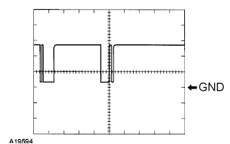
Reference: Terminal SIL - PGND Tool setting 5 V/DIV, 1 ms/DIV Condition Communication established by connecting intelligent tester to DLC3 -
Waveform 2
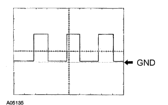
Reference: Terminal SPD - PGND Tool setting 5 V/DIV, 20 ms/DIV Condition Vehicle speed approximately 20 km/h -
Waveform 3
Reference: Terminal TACH- PGND Tool setting 5 V/DIV, 10 ms/DIV Condition Idling