ELECTRONIC POWER STEERING SYSTEM TEST MODE PROCEDURE

Note
The steering zero point calibration is performed when conducting the test mode inspection after the power steering computer assembly has been replaced with a new one.
Tech Tips
-
In test mode, speed sensor signals and engine speed sensor signals can be checked easily.
-
Test mode codes C1571/71 and C1573/73 are recorded during transition to test mode. These codes do not indicate malfunctions since the codes are cleared when the ECU determines the sensor is normal.
-
Test mode codes are cleared simultaneously when test mode is terminated.
-
TEST MODE START-UP (USING INTELLIGENT TESTER)
-
Connect the intelligent tester to the DLC3.
-
Turn the ignition switch ON and turn on the tester. On the tester, select the following menu items: Chassis / EMPS / Utility / Signal check / All signal check or One signal check.
Tech Tips
The warning light starts to blink when entering test mode
-
-
TEST MODE START-UP (USING SST CHECK WIRE)
-
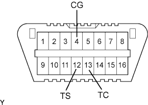
Turn the ignition switch OFF and make a short circuit between terminals 12 (TS) and 4 (CG) of the DLC3 using SST.
- SST
- 09843-18040
Note
-
Be sure to connect the correct terminals of the connector, otherwise a malfunction may occur.
Tech Tips
If the steering zero point calibration has not been performed, the zero point calibration is performed when entering test mode.
-
-
CHECK TEST MODE DISPLAY
-
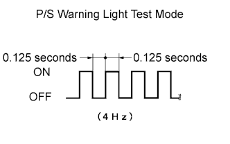
The P/S warning light blinks as shown on the left when entering test mode.
Tech Tips
If the steering zero point calibration has not been performed, the P/S warning light comes on until the zero point calibration is completed, and shows the test mode blink pattern after the zero point calibration is completed.
-
-
CHECK VEHICLE SPEED SIGNAL AND ENGINE REVOLUTION SIGNAL
-
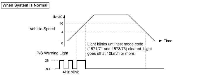
Drive the vehicle until the vehicle speed reaches 10 km/h or more.
-
-
READ TEST MODE CODE
-
Check DTCs in test mode using the intelligent tester.
Tech Tips
Test mode codes are cleared when leaving test mode.
-
-
READ TEST MODE CODE (USING SST CHECK WIRE)
-
Turn the ignition switch OFF and make a short circuit between terminal 12 (TS) and terminal 4 (CG) , and also make a short circuit between terminal 13 (TC) and terminal 4 (CG) of the DLC3 using SST.
- SST
- 09843-18040
Note
-
Be sure to connect the correct terminals of the connector, otherwise a malfunction may occur.
-
The vehicle must be stationary.
-
Test mode codes are cleared when leaving test mode (open between terminals 12 (TS) and 4 (CG)).
-
Read the number of times that the P/S warning light on the combination meter blinks.
Tech Tips
-
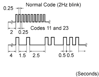
In normal code, the P/S warning light comes on for 0.25 seconds at intervals of 0.25 seconds (2Hz blink).
-
When outputting a DTC, the P/S warning light displays it at intervals of 4 seconds. When outputting two or more DTCs, the light displays each DTC at intervals of 2.5 seconds, and repeats from the first one 4 seconds after indicating the last one.
-
If 2 or more malfunctions are detected at the same time, DTCs are displayed in ascending numerical order.
-
-
-
END OF TEST MODE
-
Return to normal mode by following the instructions displayed on the intelligent tester.
-
Turn the ignition switch OFF and disconnect the tester.
-
-
END OF TEST MODE (USING SST CHECK WIRE)
-
Turn the ignition switch OFF and open between terminals 13 (TC) and terminal 4 (CG), and between terminals 12 (TS) and 4 (CG) of the DLC3.
- SST
- 09843-18040
-
Turn the ignition switch ON.
TEST MODE CODE Code Detection Item Conditions to Clear Code Trouble Areas
(Clearing code cannot start normal mode)
C1571/71 Vehicle speed check Meter vehicle signal 10 km/h or more
-
Speed sensor
-
Brake actuator assembly (built-in skid control) ECU
-
Combination meter
-
Power steering ECU assembly
-
Wire harness and connector
C1573/73 Engine revolution signal check Engine revolution signal 300 r/min or more
-
Engine speed sensor
-
ECM
-
Power steering ECU assembly
-
Wire harness and connector
-