POWER STEERING ECU REMOVAL

-
REMOVE INSTRUMENT PANEL ASSEMBLY
-
REMOVE COWL SIDE TRIM BOARD LH
-
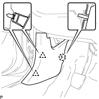
Disengage the 2 clips and claw, and remove the cowl side trim board LH.
-
-
REMOVE COWL SIDE TRIM BOARD RH
Tech Tips
Perform the same procedure as for the LH.
-
REMOVE HEATER CONTROL ASSEMBLY (for LHD)
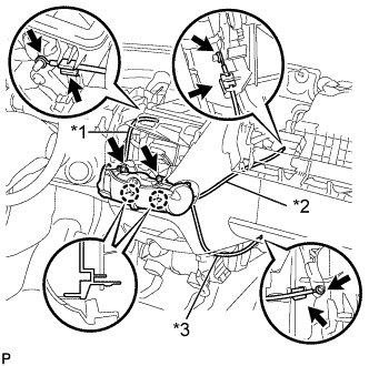
Text in Illustration *1 Defroster Cable *2 Air Inlet Cable *3 Air Mix Cable Note
Do not bend the cable when removing the heater control assembly.
-
Separate the black air mix cable from the clamp and remove the cable ring from the temperature control link.
-
Separate the white air inlet cable from the clamp and remove the cable ring from the air inlet control link.
-
Separate the blue defroster cable from the clamp and remove it from the mode link.
-
Remove the 2 screws, disengage the 2 claws and remove the heater control assembly.
-
-
REMOVE HEATER CONTROL ASSEMBLY (for RHD)
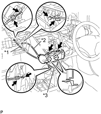
Text in Illustration *1 Air Inlet Cable *2 Defroster Cable *3 Air Mix Damper Cable Note
Do not bend the cable when removing the heater control assembly.
-
Separate the black air mix cable from the clamp and remove the cable ring from the temperature control link.
-
Separate the white air inlet cable from the clamp and remove the cable ring from the air inlet control link.
-
Separate the blue defroster cable from the clamp and remove it from the mode link.
-
Remove the 2 screws, disengage the 2 claws and remove the heater control assembly.
-
-
REMOVE FLOOR SHIFT POSITION INDICATOR HOUSING SUB-ASSEMBLY (for Multi-Mode Manual Transaxle)
-
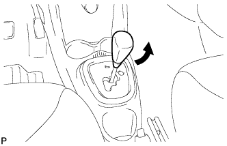
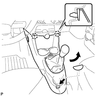
Turn the shift knob in the direction indication by the arrow in the illustration to remove it.
-
Disengage the 4 claws and remove the floor shift position indicator housing sub-assembly
-
-
REMOVE CONSOLE BOX (for Multi-Mode Manual Transaxle)
-
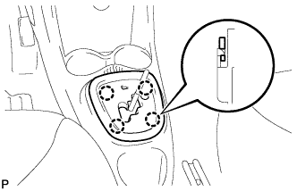
Remove the box bottom mat.
-
Remove the bolt <B>.
-
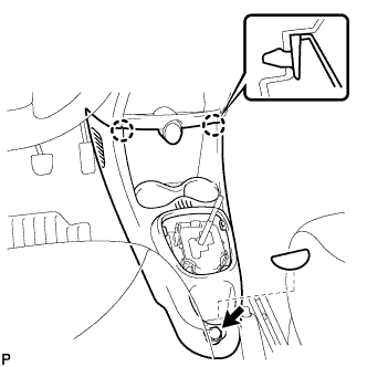
Disengage the 2 claws and remove the console box.
-
-
REMOVE CONSOLE BOX (for Manual Transaxle)
-
Turn the shift knob in the direction indication by the arrow in the illustration to remove it.
-
Remove the box bottom mat.
-
Remove the bolt <B>.
-
Disengage the 2 claws and remove the console box.
-
-
REMOVE INSTRUMENT PANEL ASSEMBLY LOWER
-
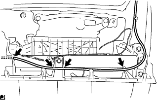
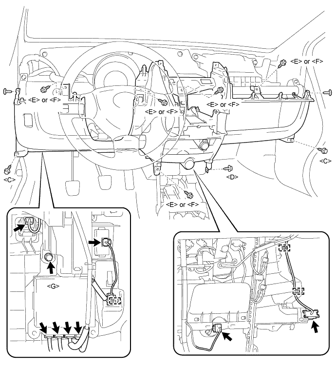
Disconnect the antenna cord by disengaging the 4 fastenings.
-
Disconnect the connectors and disengage the 3 wire harness clamps.
-
Remove the 2 bolts <C>, 5 screws <E> or <F>, screw <D>, screw <G> and 2 clips and remove the instrument panel lower.
-
-
REMOVE POWER STEERING ECU ASSEMBLY
-
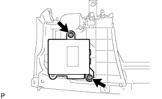
Remove the 2 bolts and the power steering ECU assembly from the instrument panel assembly lower.
-