POWER STEERING ECU REMOVAL

CAUTION:
Some of these service operations affect the SRS airbag system. Be sure to read the precautionary notices concerning the SRS airbag system before servicing Click here.
-
DISCONNECT CABLE FROM NEGATIVE BATTERY TERMINAL
-
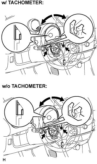
REMOVE STEERING COLUMN UPPER COVER
-
Remove the 2 screws while turning the steering wheel to the right and left.
-
Disengage the 4 claws and remove the steering column cover upper.
-
Remove the steering column cover upper, as shown in the illustration (w/ tachometer).
-
If the steering column cover upper is difficult to remove, loosen the screw behind the tachometer, pull up and extend the tachometer, and then remove the steering cover upper (w/ tachometer).
-
-
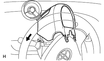
REMOVE STEERING COLUMN LOWER COVER
-
Remove the screw and steering column lower cover.
-
-
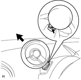
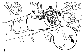
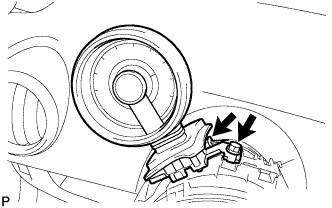
REMOVE TACHOMETER (w/ Tachometer)
-
Disconnect the connector.
-
Remove the bolt and tachometer.
-
-
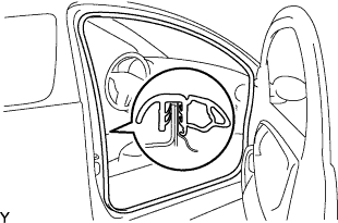
REMOVE FRONT DOOR OPENING TRIM WEATHERSTRIP RH
-
Remove the front door opening trim weatherstrip.
-
-
REMOVE FRONT DOOR OPENING TRIM WEATHERSTRIP LH
Tech Tips
Perform the same procedure as for the RH.
-
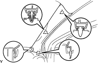
REMOVE FRONT PILLAR GARNISH RH
-
Disengage the 2 clips and 2 claws, and remove the front pillar garnish.
-
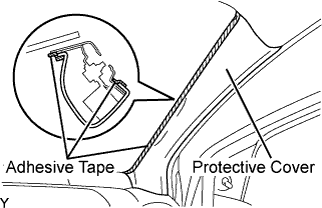
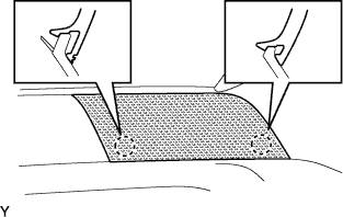
Completely cover the airbag with a piece of cloth or nylon of 700 mm (27.56 in.) x 120 mm (4.72 in.) and fix the ends of the cover with adhesive tape, as shown in the illustration.
Note
Cover the curtain shield airbag with the protective cover as soon as the front pillar garnish is removed.
-
-
REMOVE FRONT PILLAR GARNISH LH
Tech Tips
Perform the same procedure as for the RH.
-
REMOVE INSTRUMENT PANEL SPEAKER PANEL SUB-ASSEMBLY NO.1
-
Disengage the 2 claws.
-
-
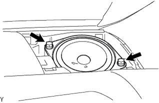
REMOVE FRONT NO.1 SPEAKER ASSEMBLY
-
Remove the 2 screws.
-
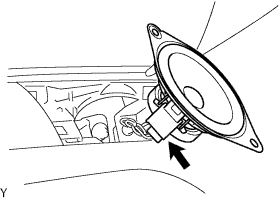
Disconnect the connector.
-
-
REMOVE INSTRUMENT PANEL SPEAKER PANEL SUB-ASSEMBLY NO.2
Tech Tips
Perform the same procedure as for the No. 1.
-
REMOVE FRONT NO.1 SPEAKER ASSEMBLY
Tech Tips
Perform the same procedure as for the RH.
-
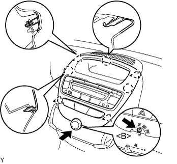
REMOVE INSTRUMENT CLUSTER PANEL SUB-ASSEMBLY CENTER
-
Remove the control knob.
-
Remove the screw <B>.
-
Disengage the 4 clips and 3 claws and remove the cluster finish panel by pulling it up from underneath.
-
Disconnect the connectors and remove the instrument cluster finish panel center.
-
-
REMOVE INSTRUMENT PANEL ASSEMBLY
-
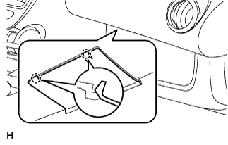
Disengage the 2 claws and open the cover.
-
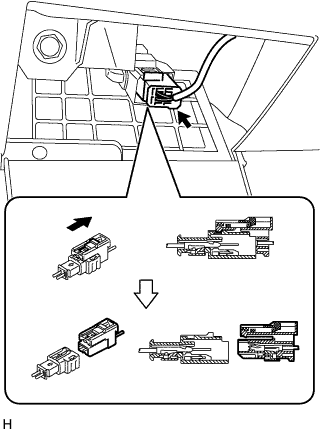
Disconnect the airbag connector, as shown in the illustration.
-
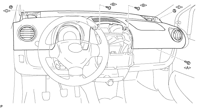
Remove the bolt <A>, 2 nuts <D> and 2 screws <B>.
-
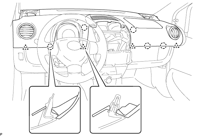
Disengage the 4 clips and 5 claws and remove the instrument panel assembly.
-
-
REMOVE COWL SIDE TRIM BOARD LH
-
Disengage the 2 clips and claw, and remove the cowl side trim board LH.
-
-
REMOVE COWL SIDE TRIM BOARD RH
Tech Tips
Perform the same procedure as for the LH.
-
REMOVE HEATER CONTROL ASSEMBLY (for LH)
-
Pinch portion A to release the clamp.
-
Remove the cable ring from the air inlet lever.
-
-
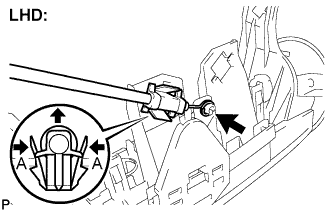
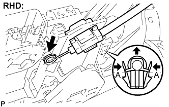
REMOVE HEATER CONTROL ASSEMBLY (for RH)
-
Pinch portion A to release the clamp.
-
Remove the cable ring from the air inlet lever.
-
-
REMOVE CONSOLE BOX
-
Remove the shift knob.
-
Remove the box bottom mat.
-
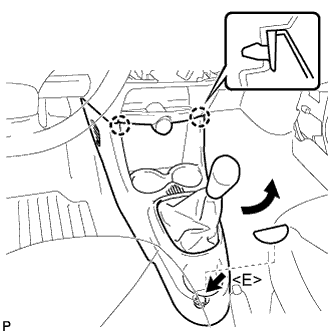
Remove the bolt <E>.
-
Disengage the 2 claws and remove the console box.
-
-
REMOVE INSTRUMENT PANEL ASSEMBLY LOWER
-
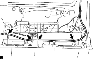
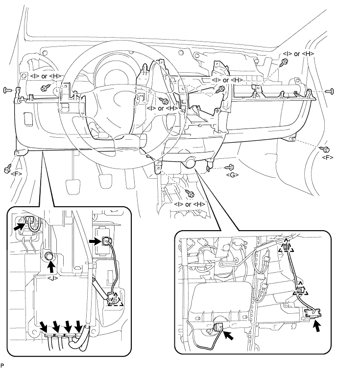
Disconnect the antenna cord by disengaging the 4 fastenings.
-
Disconnect the connectors and 3 wire harness clamps.
-
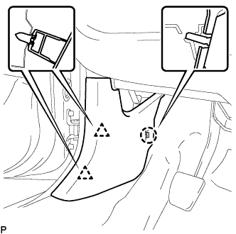
Remove the 2 bolts <F>, 5 screws <I> or <H>, screw <G>, screw <J> and 2 clips and remove the instrument panel lower.
-
-
REMOVE POWER STEERING ECU ASSEMBLY
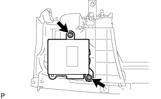
-
Remove the 2 bolts and power steering ECU assembly from the instrument panel assembly lower.
-