STEERING GEAR HOUSING REMOVAL

-
POSITION WHEELS FACING STRAIGHT AHEAD
-
DISCONNECT CABLE FROM NEGATIVE BATTERY TERMINAL
-
REMOVE ENGINE COVER (for 2WZ-TV)
-
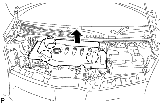
Disengage the 3 claws and remove the engine cover.
-
-
REMOVE AIR HOSE (for 2WZ-TV)
-
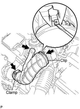
Loosen the clamp bolt.
-
Using a screwdriver and pliers, remove the clip.
-
Remove the air hose.
-
-
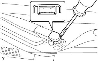
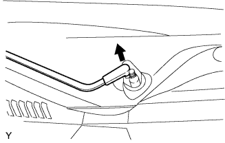
REMOVE FRONT WIPER ARM HEAD CAP
-
Using a screwdriver with its tip wrapped in protective tape, remove the front wiper arm head cap.
-
-
REMOVE FRONT WIPER ARM LH
-
Operate the wiper, then stop the windshield wiper motor assembly in the automatic stop position.
-
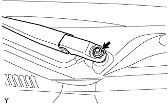
Remove the nut and front wiper main arm.
-
Disengage the meshing of the secondary arm from the front wiper motor and link assembly.
Note
Do not bend the secondary arm when removing it.
-
-
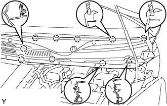
REMOVE HOOD TO COWL TOP SEAL

-
Disengage the 8 clips and remove the hood to cowl top seal.
-
-
REMOVE COWL TOP VENTILATOR LOUVER LH
-
Remove the clip.
-
Disengage the 9 claws and remove the cowl top ventilator louver LH.
-
Disconnect the washer hose.
-
-
REMOVE COWL TOP VENTILATOR LOUVER RH

-
Remove the clip.
-
Disengage the 8 claws and remove the cowl top ventilator louver RH.
-
Disconnect the washer hose.
-
-
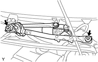
REMOVE FRONT WIPER MOTOR AND LINK ASSEMBLY
-
Remove the 2 bolts.
-
Disconnect the connector and remove the front wiper motor and link assembly.
-
-
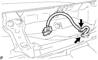
REMOVE COWL TOP PANEL OUTER
-
Remove the clamp of the wire harness.
-
Remove the grommet of the wire harness.
-
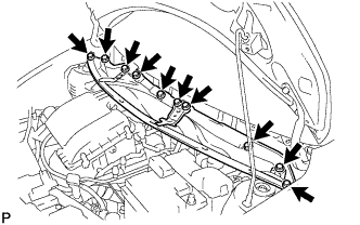
Remove the 10 bolts and cowl top panel.
-
-
REMOVE STEERING COLUMN HOLE COVER PLATE
-
Turn back the floor carpet and disengage the 2 claws from the steering hole cover plate.
-
-
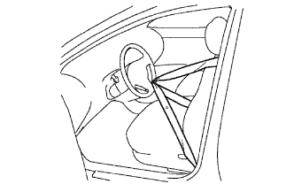
SEPARATE STEERING INTERMEDIATE SHAFT ASSEMBLY NO. 2
-
Hold the steering wheel assembly with the seat belt in order to prevent rotation and damage to the spiral cable.
-
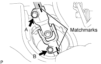
Place matchmarks on the sliding yoke sub-assembly and the intermediate shaft.
-
Loosen bolt A and remove bolt B to separate the sliding yoke sub-assembly.
-
-
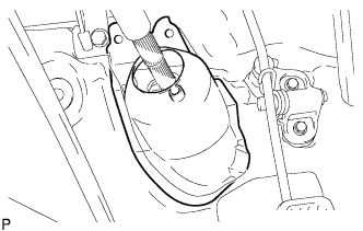
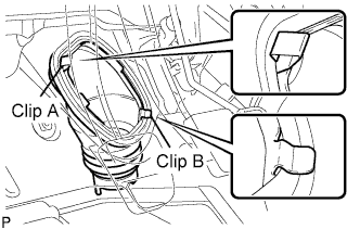
SEPARATE STEERING COLUMN HOLE COVER SUB-ASSEMBLY NO. 1
-
Remove clip A and separate the steering column hole cover from the body.
Note
Do not damage clip B.
-
-
REMOVE FRONT WHEEL
-
SEPARATE TIE ROD END SUB-ASSEMBLY LH
-
Remove the cotter pin and castle nut.
-
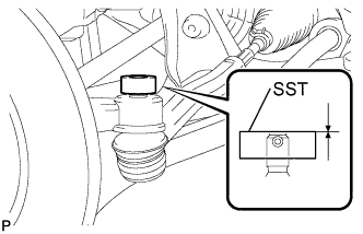
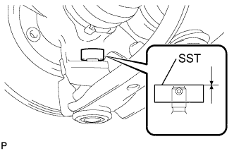
Install SST (spacer B) to the threaded section of the tie rod end.
- SST
- 09960-20010 ( 09961-02060 )
Tech Tips
Make sure the upper ends of the threaded section of the tie rod end and SST (spacer B) are aligned.
-
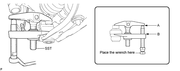
Using SST, separate the tie rod end from the front axle assembly.
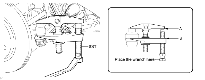
- SST
- 09960-20010 ( 09961-02010 )
Note
-
Make sure to tie the string of SST to the vehicle to prevent SST from dropping.
-
Install SST so that A and B are parallel.
-
Be sure to place the wrench on the part indicated in the illustration.
-
Do not damage the ball joint dust cover.
-
Do not damage the front disc brake dust cover.
-
-
SEPARATE TIE ROD END SUB-ASSEMBLY RH
Tech Tips
Perform the same procedure as for the LH side.
-
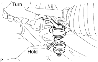
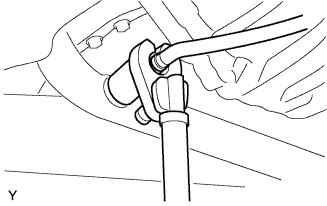
SEPARATE FRONT STABILIZER BAR
-
Hold the bolt with a spanner (10 mm) and remove the nut.
-
Remove the 2 cushion retainers and 2 cushions, and separate the front stabilizer bar.
-
-
SEPARATE FRONT SUSPENSION ARM SUB-ASSEMBLY LOWER NO. 1 LH
-
Remove the clip and castle nut.
-
Install SST (spacer B) to the threaded section of the lower ball joint.
- SST
- 09960-20010 ( 09961-02060 )
Tech Tips
Make sure the upper ends of the threaded section of the lower ball joint and SST (spacer B) are aligned.
-
Using SST, separate the lower arm.
- SST
- 09960-20010 ( 09961-02010 )
Note
-
Make sure to tie the string of SST to the vehicle to prevent SST from dropping.
-
Install SST so that A and B are parallel.
-
Be sure to place the wrench on the part indicated in the illustration.
-
Do not damage the lower ball joint dust cover.
-
Do not damage the drive shaft outboard joint boots.
-
Do not damage the front disc brake dust cover.
-
-
SEPARATE FRONT SUSPENSION ARM SUB-ASSEMBLY LOWER NO. 1 RH
Tech Tips
Perform the same procedure as for the LH side.
-
REMOVE OXYGEN SENSOR (for 1KR-FE)
- SST
- 09224-00010
-
Disconnect the oxygen sensor connector.
-
Remove the oxygen sensor.
-
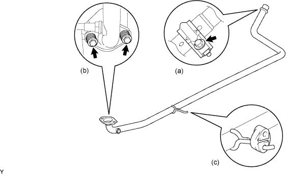
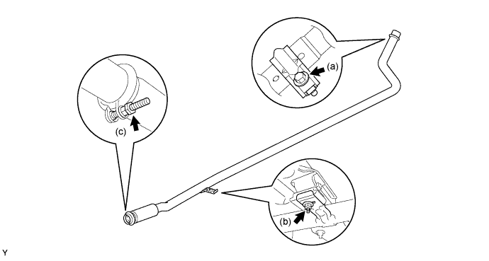
REMOVE EXHAUST PIPE ASSEMBLY FRONT (1KR-FE)
-
Remove the bolt and clamp.
-
Remove the 2 bolts, 2 compression springs and exhaust pipe gasket.
-
Remove the exhaust pipe No.4 support and exhaust front pipe assembly.
-
-
REMOVE EXHAUST PIPE ASSEMBLY FRONT (for 2WZ-TV)
-
Remove the bolt and clamp.
-
Remove the exhaust front pipe stay nut and exhaust pipe support No.4.
-
Remove the nut, clamp and the exhaust front pipe assembly.
-
-
SUSPEND ENGINE ASSEMBLY
-
for 1KR-FE:
-
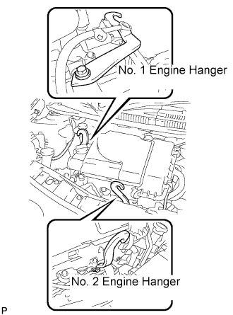
Install the No. 1 and No. 2 engine hangers, oriented in the correct directions.
Part No. No. 1 engine hanger : 12281 - 40030 No. 2 engine hanger : 12282 - 40010 Bolt 91671 - 80820 - Torque:
- 28 N*m { 286 kgf*cm, 21 ft.*lbf }
-
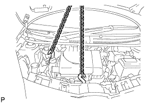
Attach the engine sling device to the engine hangers.
CAUTION:
Do not hang the engine by hooking the chain to any other parts.
-
-
for 2WZ-TV:
-
Attach the engine sling device and suspend the engine with the chain block.
-
-
-
REMOVE FRONT SUSPENSION CROSSMEMBER SUB-ASSEMBLY
-
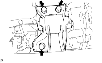
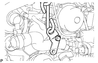
Remove the 3 bolts, then separate the engine mounting control bracket (for 1KR-FE).
-
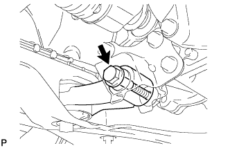
Remove the bolt, then separate the control rod from the engine mounting control bracket (for 2WZ-TV).
-
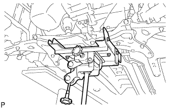
Using a transmission jack, support the front suspension crossmember sub-assembly.
-
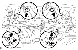
Remove the 6 bolts and the front suspension crossmember sub-assembly.
-
-
REMOVE STEERING GEAR ASSEMBLY
-
Remove the steering column hole cover from the steering gear assembly.
-
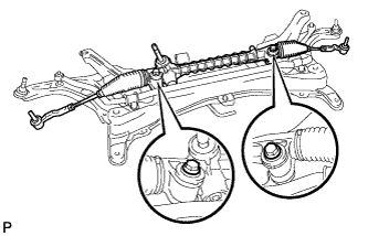
Remove the 2 bolts, 2 nuts and the steering gear assembly from the suspension crossmember sub-assembly.
-