BRAKE BOOSTER (for LHD) INSTALLATION

-
INSTALL MASTER CYLINDER PUSH ROD CLEVIS
-
Install the master cylinder push rod clevis to the brake booster assembly.
Tech Tips
Tighten the lock nut after adjusting the brake pedal height.
-
-
INSTALL CHECK VALVE GROMMET
-
Install the check valve grommet to the brake booster assembly.
-
-
INSTALL BRAKE BOOSTER ASSEMBLY
-
Install a new gasket onto the brake booster assembly.
-
Install the brake booster assembly with the 4 nuts.
- Torque:
- 16 N*m { 163 kgf*cm, 12 ft.*lbf }
-
Install the vacuum hose assembly to the brake booster assembly.
-
-
INSTALL MASTER CYLINDER PUSH ROD CLEVIS
-
Apply lithium soap base glycol grease to the push rod pin.
-
Install the push rod clevis with the push rod pin and clip.
-
-
INSTALL BRAKE ACTUATOR ASSEMBLY (w/o VSC)
-
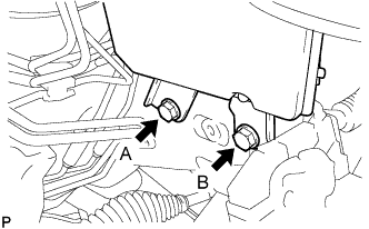
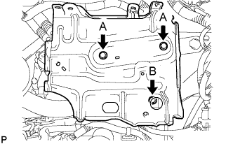
Install the brake actuator with bracket with the 2 bolts.
-
Temporarily tighten bolt B.
-
Fully tighten bolts A and B.
- Torque:
- 19 N*m { 194 kgf*cm, 14 ft.*lbf }
Note
-
Do not damage the brake tubes.
-
Tighten the bolts in order, from A to B as shown.
-
-
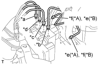
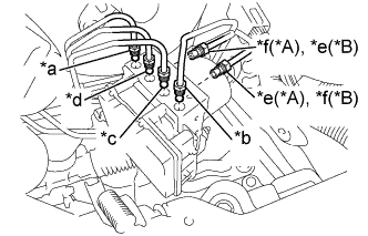
Text in Illustration *A for LHD *B for RHD *a To front wheel cylinder RH *b To front wheel cylinder LH *c To rear wheel cylinder RH *d To rear wheel cylinder LH *e From 1st master cylinder *f From 2nd master cylinder Temporarily install each brake tube to the correct positions of the brake actuator assembly as shown in the illustration.
-
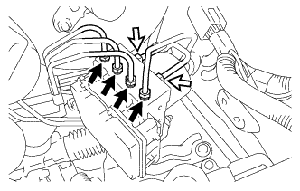
Using a union nut wrench 10 mm, install the 6 brake tubes onto the brake actuator assembly.
- Torque:
- 15 N*m { 155 kgf*cm, 11 ft.*lbf }
Note
Use the formula to calculate special torque values for situations where a union nut wrench is combined with a torque wrench Click here.
-
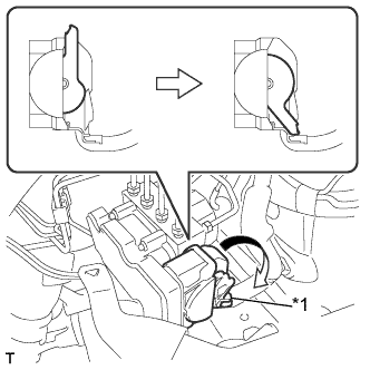
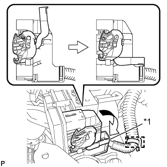
Text in Illustration *1 Lock Lever Connect the brake actuator connector and push the lock lever downward.
Note
-
Make sure that the connector is locked securely.
-
Make sure that the actuator connector can be connected smoothly. Do not allow entry of water, oil or dirt.
-
-
-
INSTALL BRAKE ACTUATOR ASSEMBLY (w/ VSC)
-
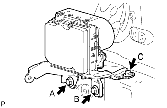
Install the brake actuator with bracket with the 3 bolts.
-
Temporarily tighten bolt C.
-
Fully tighten bolts A, B and C.
- Torque:
- 19 N*m { 194 kgf*cm, 14 ft.*lbf }
Note
-
Do not damage the brake tubes.
-
Tighten the bolts in order, from A to C as shown.
-
-
Engage the fuel tube clamp onto the brake actuator bracket assembly.
-
Text in Illustration *A for LHD *B for RHD *a To front wheel cylinder RH *b To front wheel cylinder LH *c To rear wheel cylinder RH *d To rear wheel cylinder LH *e From 1st master cylinder *f From 2nd master cylinder Temporarily install each brake tube to the correct positions of the brake actuator assembly as shown in the illustration.
-
Using a union nut wrench 10 mm and a union nut wrench 12 mm, install the 6 brake tubes onto the brake actuator assembly.
Text in Illustration 
Flare Nut 10 mm 
Flare Nut 12 mm - Torque:
- Flare Nut 10 mm
- 15 N*m { 155 kgf*cm, 11 ft.*lbf }
- Flare Nut 12 mm
- 20 N*m { 199 kgf*cm, 14 ft.*lbf }
Note
Use the formula to calculate special torque values for situations where a union nut wrench is combined with a torque wrench Click here.
-
Text in Illustration *1 Lock Lever Connect the brake actuator connector and push the lock lever downward.
Note
-
Make sure that the connector is locked securely.
-
Make sure that the actuator connector can be connected smoothly. Do not allow entry of water, oil or dirt.
-
-
Connect the wire harness clamp.
-
-
INSTALL BATTERY CLAMP SUB-ASSEMBLY
-
Install the battery clamp sub-assembly with the 3 bolts.
- Torque:
- Bolt A
- 7.4 N*m { 75 kgf*cm, 65 in.*lbf }
- Bolt B
- 17 N*m { 175 kgf*cm, 13 ft.*lbf }
-
-
INSTALL BRAKE MASTER CYLINDER SUB-ASSEMBLY
-
INSPECT AND ADJUST BRAKE PEDAL
-
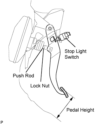
Inspect the brake pedal height.
Pedal height from floor Steering Position Standard for LHD 135.8 to 145.8 mm (5.346 to 5.740 in.) for RHD 121.6 to 131.6 mm (4.787 to 5.181 in.) If the pedal height is incorrect, adjust it.
-
Adjust the brake pedal height.
-
Disconnect the connector from the stop light switch.
-
Turn the stop light switch counterclockwise, and remove the stop light switch.
-
Loosen the push rod lock nut.
-
Adjust the pedal height by turning the pedal push rod.
-
Tighten the push rod lock nut.
- Torque:
- 22 N*m { 224 kgf*cm, 16 ft.*lbf }
-
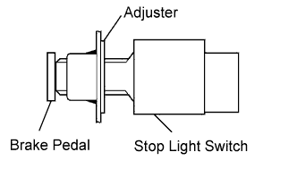
Insert the stop light switch into the adjuster until it slightly touches the brake pedal.
Note
Do not depress the brake pedal.
-
Make a quarter turn clockwise to install the stop light switch.
Note
Do not depress the brake pedal.
Tech Tips
The turning torque for installing the stop light switch:
- Torque:
- 1.5 N*m { 15 kgf*cm, 13 in.*lbf, or less }
-
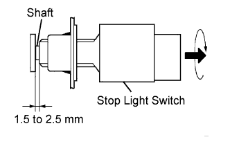
Check the stop light switch clearance.
Stop light switch clearance 1.5 to 2.5 mm (0.059 to 0.098 in.) -
Connect the connector to the stop light switch.
-
-
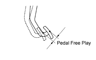
Inspect the brake pedal free play.
-
Stop the engine and depress the brake pedal several times until there is no more vacuum left in the booster.
-
Push in the pedal until slight resistance is felt. Measure the distance as shown.
Pedal free play 1.0 to 6.0 mm (0.039 to 0.236 in.) If incorrect, troubleshoot the brake system.
-
-
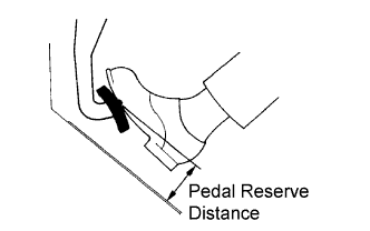
Inspect the brake pedal reserve distance.
-
Release the parking brake lever. With the engine running, depress the pedal and measure the pedal reserve distance as shown.
Pedal reserve distance from floor Specification Condition Standard for 1KR-FE for LHD 490 N (50 kgf, 110.2 lbf) More than 84 mm (3.31 in.) for RHD More than 77 mm (3.03 in.) for 2WZ-TV for LHD More than 79 mm (3.11 in.) for RHD More than 71 mm (2.80 in.) If incorrect, troubleshoot the brake system.
-
-
-
INSPECT FOR BRAKE FLUID LEAK