BRAKE BOOSTER (for LHD) INSTALLATION

-
INSTALL MASTER CYLINDER PUSH ROD CLEVIS
-
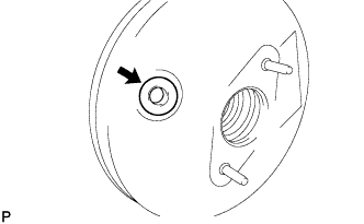
INSTALL CHECK VALVE GROMMET
-
Install the grommet onto the brake booster.
-
-
INSTALL BRAKE BOOSTER ASSEMBLY
-
Install a new gasket onto the brake booster.
-
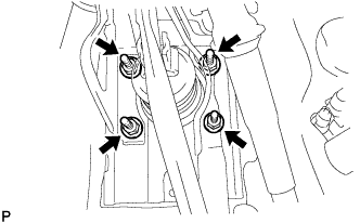
Install the brake booster with the 4 nuts.
- Torque:
- 31 N*m { 311 kgf*cm, 23 ft.*lbf }
- From VIN VF7PM8HTC89700129
- 16 N*m { 163 kgf*cm, 12 ft.*lbf }
-
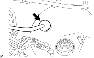
Connect the vacuum hose to the brake booster.
-
-
INSTALL MASTER CYLINDER PUSH ROD CLEVIS
-
Apply lithium soap base glycol grease to the push rod pin.
-
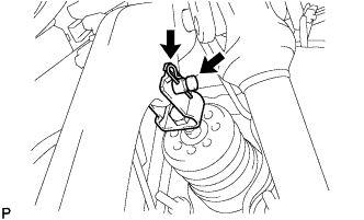
Install the push rod clevis with the push rod pin and clip.
-
-
INSTALL BRAKE MASTER CYLINDER
-
Install a new O-ring onto the master cylinder.
-
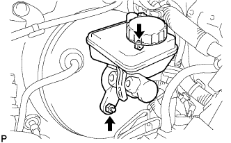
Install the master cylinder onto the brake booster with the 2 nuts.
- Torque:
- 20 N*m { 204 kgf*cm, 15 ft.*lbf }
-
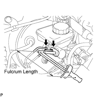
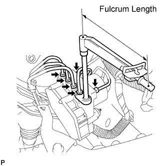
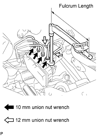
Using a 10 mm union nut wrench, install the 2 brake tubes to the master cylinder (w/o VSC).
- Torque:
- without 10 mm union nut wrench
- 15 N*m { 155 kgf*cm, 11 ft.*lbf }
- with 10 mm union nut wrench
- 14 N*m { 143 kgf*cm, 10 ft.*lbf }
Note
-
This torque value can be obtained by using a torque wrench with a fulcrum length of 300 mm (11.8 in.) and a 10 mm union nut wrench with a fulcrum length of 22 mm (0.886 in.) Click here.
-
This torque value is effective when the union nut wrench is parallel to a torque wrench.
-
Using a 12 mm union nut wrench, install the 2 brake tubes to the master cylinder (w/ VSC).
- Torque:
- without 12 mm union nut wrench
- 20 N*m { 204 kgf*cm, 15 ft.*lbf }
- with 12 mm union nut wrench
- 18 N*m { 184 kgf*cm, 13 ft.*lbf }
Note
-
This torque value can be obtained by using a torque wrench with a fulcrum length of 300 mm (11.8 in.) and a 12 mm union nut wrench with a fulcrum length of 30 mm (1.18 in.) Click here.
-
This torque value is effective when the union nut wrench is parallel to a torque wrench.
-
Connect the brake fluid level warning switch connector.
-
-
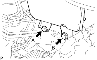
INSTALL BRAKE ACTUATOR ASSEMBLY (w/o VSC)
-
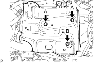
Install the actuator with bracket with the 2 bolts.
-
Provisionally tighten bolt B.
-
Fully tighten bolts A and B.
- Torque:
- 19 N*m { 194 kgf*cm, 14 ft.*lbf }
Note
-
Do not damage the brake tubes.
-
Tighten the bolts in order, from A to B as shown.
-
-
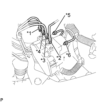
Temporarily install each brake tube to the correct positions of the brake actuator as shown in the illustration.
Tech Tips
-
*1: To front wheel cylinder RH
-
*2: To front wheel cylinder LH
-
*3: To rear wheel cylinder RH
-
*4: To rear wheel cylinder LH
-
*5: From 1st master cylinder
-
*6: From 2nd master cylinder
-
-
Using a 10 mm union nut wrench, install the 6 brake tubes onto the brake actuator.
- Torque:
- without 10 mm union nut wrench
- 15 N*m { 155 kgf*cm, 11 ft.*lbf }
- with 10 mm union nut wrench
- 14 N*m { 143 kgf*cm, 10 ft.*lbf }
Note
-
This torque value can be obtained by using a torque wrench with a fulcrum length of 300 mm (11.8 in.) and a 10 mm union nut wrench with a fulcrum length of 22 mm (0.886 in.) Click here.
-
This torque value is effective when the union nut wrench is parallel to a torque wrench.
-
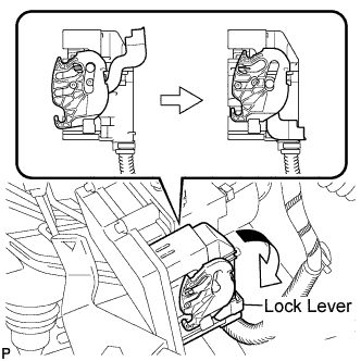
Connect the connector and push the lock lever downward.
Note
Lock the connector securely.
-
-
INSTALL BRAKE ACTUATOR ASSEMBLY (w/ VSC)
-
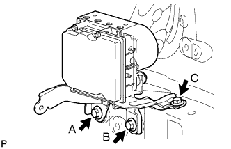
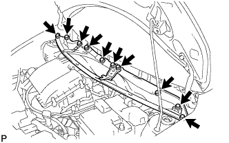
Install the actuator with bracket with the 3 bolts.
-
Provisionally tighten bolt C.
-
Fully tighten bolts A, B and C.
- Torque:
- 19 N*m { 194 kgf*cm, 14 ft.*lbf }
Note
-
Do not damage the brake tubes.
-
Tighten the bolts in order, from A to C as shown.
-
-
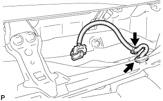
Connect the fuel tube clamp onto the brake actuator bracket.
-
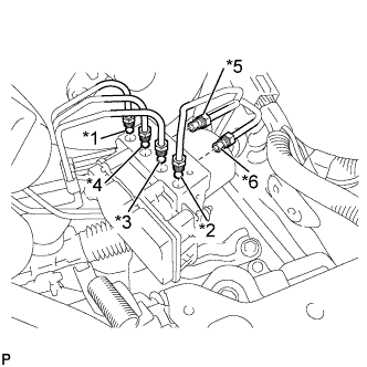
Temporarily install each brake tube into the correct positions on the brake actuator as shown in the illustration.
Tech Tips
-
*1: To front wheel cylinder RH
-
*2: To front wheel cylinder LH
-
*3: To rear wheel cylinder RH
-
*4: To rear wheel cylinder LH
-
*5: From 1st master cylinder
-
*6: From 2nd master cylinder
-
-
Using a 10 mm union nut wrench, install the 4 brake tubes onto the brake actuator.
- Torque:
- without 10 mm union nut wrench
- 15 N*m { 155 kgf*cm, 11 ft.*lbf }
- with 10 mm union nut wrench
- 14 N*m { 143 kgf*cm, 10 ft.*lbf }
Note
-
This torque value can be obtained by using a torque wrench with a fulcrum length of 300 mm (11.8 in.) and a 10 mm union nut wrench with a fulcrum length of 22 mm (0.886 in.) Click here.
-
This torque value is effective when the union nut wrench is parallel to a torque wrench.
-
Using a 12 mm union nut wrench, install the 2 brake tubes onto the brake actuator.
- Torque:
- without 12 mm union nut wrench
- 20 N*m { 204 kgf*cm, 15 ft.*lbf }
- with 12 mm union nut wrench
- 18 N*m { 184 kgf*cm, 13 ft.*lbf }
Note
-
This torque value can be obtained by using a torque wrench with a fulcrum length of 300 mm (11.8 in.) and a 12 mm union nut wrench with a fulcrum length of 30 mm (1.18 in.) Click here.
-
This torque value is effective when the union nut wrench is parallel to a torque wrench.
-
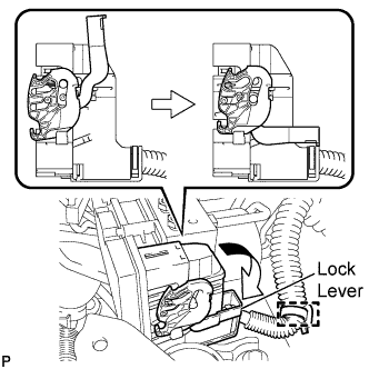
Connect the connector and push the lock lever downward.
Note
Lock the connector securely.
-
Connect the wire harness clamp.
-
-
INSTALL BATTERY CLAMP SUB-ASSEMBLY
-
Install the battery clamp with the 3 bolts.
- Torque:
- Bolt A
- 7.4 N*m { 75 kgf*cm, 65 in.*lbf }
- Bolt B
- 17 N*m { 175 kgf*cm, 13 ft.*lbf }
-
Engage the 2 wire harness clamps.
-
-
INSTALL ENGINE ROOM RELAY BLOCK
-
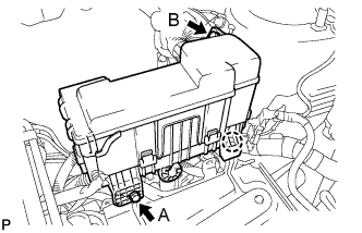
Engage the claw and install the relay block.
-
Install the 2 bolts.
- Torque:
- Bolt A
- 5.4 N*m { 55 kgf*cm, 48 in.*lbf }
- Bolt B
- 8.4 N*m { 85 kgf*cm, 74 in.*lbf }
-
-
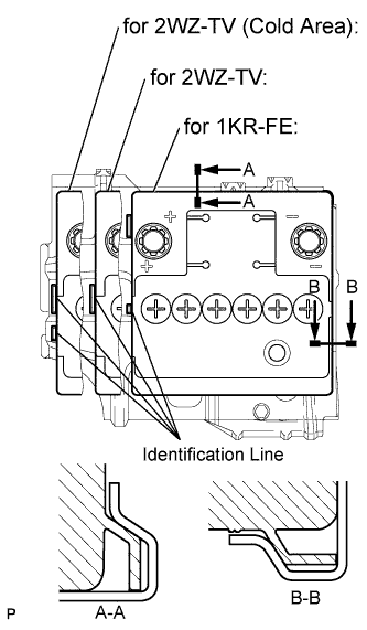
INSTALL BATTERY
-
Install the battery onto the battery clamp, as shown in the illustration.
Note
-
The identification line should be seen after installing the battery.
-
The battery clamp should be in contact with the battery after the installation.
-
-
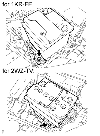
Install the battery clamp with the bolt.
- Torque:
- 15 N*m { 154 kgf*cm, 11 ft.*lbf }
-
Connect the battery positive terminal with the nut.
- Torque:
- 5.4 N*m { 55 kgf*cm, 48 in.*lbf }
-
-
FILL RESERVOIR WITH BRAKE FLUID
Fluid SAE J1704 or FMVSS No. 116 DOT4 -
BLEED BRAKE MASTER CYLINDER
Tech Tips
If the master cylinder has been disassembled or if the reservoir becomes empty, bleed the air from the master cylinder.
-
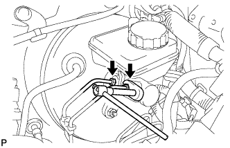
Using a 10 mm union nut wrench, separate the brake tubes from the master cylinder (w/o VSC).
-
Using a 12 mm union nut wrench, separate the brake tubes from the master cylinder (w/ VSC).
-
Slowly depress the brake pedal and hold it there (Step A).
-
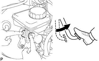
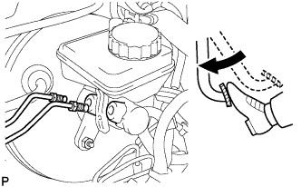
Block the outer holes with your fingers, and release the brake pedal (Step B).
-
Repeat step A and B 3 or 4 times.
-
Using a 10 mm union nut wrench, install the brake tubes to the master cylinder (w/o VSC).
- Torque:
- without 10 mm union nut wrench
- 15 N*m { 155 kgf*cm, 11 ft.*lbf }
- with 10 mm union nut wrench
- 14 N*m { 143 kgf*cm, 10 ft.*lbf }
Note
-
This torque value can be obtained by using a torque wrench with a fulcrum length of 300 mm (11.8 in.) and a 10 mm union nut wrench with a fulcrum length of 22 mm (0.886 in.) Click here.
-
This torque value is effective when the union nut wrench is parallel to a torque wrench.
-
Using a 12 mm union nut wrench, install the brake tubes to the master cylinder (w/ VSC).
- Torque:
- without 12 mm union nut wrench
- 20 N*m { 204 kgf*cm, 15 ft.*lbf }
- with 12 mm union nut wrench
- 18 N*m { 184 kgf*cm, 13 ft.*lbf }
Note
-
This torque value can be obtained by using a torque wrench with a fulcrum length of 300 mm (11.8 in.) and a 12 mm union nut wrench with a fulcrum length of 30 mm (1.18 in.) Click here.
-
This torque value is effective when the union nut wrench is parallel to a torque wrench.
-
-
BLEED BRAKE LINE
-
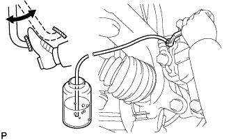
Connect a vinyl tube to the bleeder plug.
-
Depress the brake pedal several times, then loosen the bleeder plug with the pedal depressed (Step C).
-
At the point where the fluid stops coming out, tighten the bleeder plug, then release the brake pedal (Step D).
-
Repeat step C and D until all the air in the fluid is completely bled out.
-
Tighten the bleeder plug.
- Torque:
- 6.5 N*m { 66 kgf*cm, 58 in.*lbf }
-
Repeat the above procedure to bleed the air out of the brake line for each wheel.
-
-
CHECK FLUID LEVEL IN RESERVOIR
-
Check the fluid level and add fluid if necessary.
Fluid SAE J1704 or FMVSS No. 116 DOT4
-
-
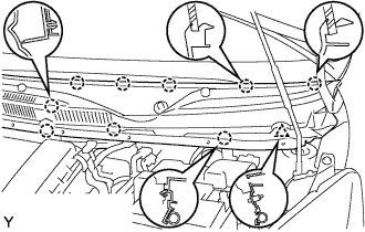
INSTALL COWL TOP PANEL OUTER
-
Install the cowl top panel with the 10 bolts.
- Torque:
- 9.2 N*m { 94 kgf*cm, 81 in.*lbf }
-
Install the grommet of the wire harness.
-
Install the clamp of the wire harness.
-
-
INSTALL FRONT WIPER MOTOR AND LINK ASSEMBLY
-
Connect the connector.
-
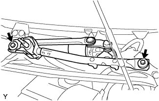
Install the front wiper motor and link assembly with the 2 bolts.
- Torque:
- 13 N*m { 127 kgf*cm, 9 ft.*lbf }
-
-
INSTALL COWL TOP VENTILATOR LOUVER RH
-
Connect the washer hose.
-

Engage the 8 claws and install the cowl top ventilator louver RH.
-
Install the clip.
-
-
INSTALL COWL TOP VENTILATOR LOUVER LH
-
Connect the washer hose.
-
Engage the 9 claws and install the cowl top ventilator louver LH.
-
Install the clip.
-
-
INSTALL HOOD TO COWL TOP SEAL

-
Engage the 8 clips and install the hood to cowl top seal.
-
-
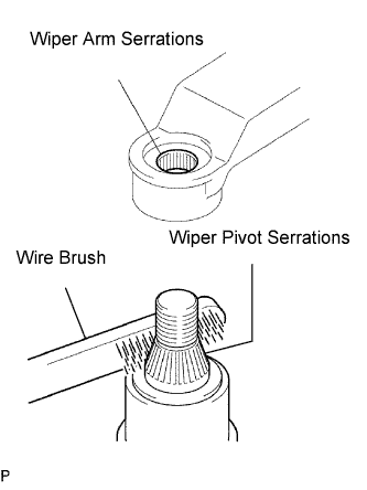
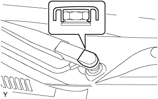
INSTALL FRONT WIPER ARM
-
Scrape any metal powder off the serrated part of the wiper arm with a round file or equivalent (when reinstalling).
-
Clean the wiper pivot serrations with a wire brush.
-
Operate the wiper, then stop the windshield wiper motor assembly in the automatic stop position.
-
Provisionally install the front wiper main arm with the nut.
-
Install the front wiper secondary arm onto the front wiper motor and link assembly.
-
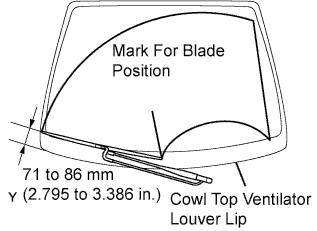
Align the blade tip with the mark on the windshield glass, as shown in the illustration.
-
Tighten the nut of the front wiper main arm.
- Torque:
- 21 N*m { 209 kgf*cm, 15 ft.*lbf }
-
-
INSTALL FRONT WIPER ARM HEAD CAP
-
Engage the claw and install the front wiper arm head cap.
-
-
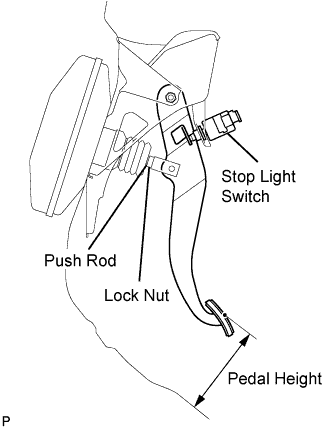
INSPECT AND ADJUST BRAKE PEDAL
-
Inspect the brake pedal height.
Pedal height from floor Steering Position Standard for LHD 135.8 to 145.8 mm (5.346 to 5.740 in.) for RHD 121.6 to 131.6 mm (4.787 to 5.181 in.) If the pedal height is incorrect, adjust it.
-
Adjust the brake pedal height.
-
Disconnect the connector from the stop light switch.
-
Turn the stop light switch counterclockwise, and remove the stop light switch.
-
Loosen the push rod lock nut.
-
Adjust the pedal height by turning the pedal push rod.
-
Tighten the push rod lock nut.
- Torque:
- 22 N*m { 224 kgf*cm, 16 ft.*lbf }
-
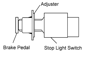
Insert the stop light switch into the adjuster until it slightly touches the brake pedal.
Note
Do not depress the brake pedal.
-
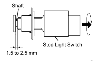
Make a quarter turn clockwise to install the stop light switch.
Note
Do not depress the brake pedal.
Tech Tips
The turning torque for installing the stop light switch:
- Torque:
- 1.5 N*m { 15 kgf*cm, 13 in.*lbf, or less }
-
Check the stop light switch clearance.
Stop light switch clearance 1.5 to 2.5 mm (0.059 to 0.098 in.) -
Connect the connector to the stop light switch.
-
-
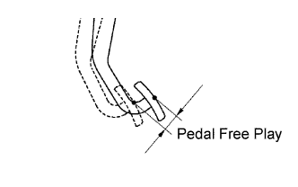
Inspect the brake pedal free play.
-
Stop the engine and depress the brake pedal several times until there is no more vacuum left in the booster.
-
Push in the pedal until slight resistance is felt. Measure the distance as shown.
Pedal free play 1.0 to 6.0 mm (0.039 to 0.236 in.) If incorrect, troubleshoot the brake system.
-
-
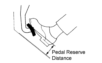
Inspect the brake pedal reserve distance.
-
Release the parking brake lever. With the engine running, depress the pedal and measure the pedal reserve distance as shown.
Pedal reserve distance from floor Specification Condition Standard for 1KR-FE for LHD 490 N (50 kgf, 110.2 lbf) More than 84 mm (3.31 in.) for RHD More than 77 mm (3.03 in.) for 2WZ-TV for LHD More than 79 mm (3.11 in.) for RHD More than 71 mm (2.80 in.) If incorrect, troubleshoot the brake system.
-
-
-
CONNECT CABLE TO NEGATIVE BATTERY TERMINAL
- Torque:
- 5.4 N*m { 55 kgf*cm, 48 in.*lbf }
-
INSPECT FOR BRAKE FLUID LEAK