BRAKE MASTER CYLINDER INSTALLATION

Note
Do not hold the piston when handling the master cylinder sub-assembly, as the piston may come out of the master cylinder sub-assembly.
-
INSTALL BRAKE MASTER CYLINDER SUB-ASSEMBLY (for LHD)
-
Install a new O-ring onto the brake master cylinder sub-assembly.
-
Install the brake master cylinder sub-assembly to the brake booster assembly with the 2 nuts.
- Torque:
- 20 N*m { 204 kgf*cm, 15 ft.*lbf }
-
Using a union nut wrench 10 mm, install the 2 brake tubes to the brake master cylinder sub-assembly (w/o VSC).
- Torque:
- 15 N*m { 155 kgf*cm, 11 ft.*lbf }
Note
Use the formula to calculate special torque values for situations where a union nut wrench is combined with a torque wrench Click here.
-
Using a union nut wrench 12 mm, install the 2 brake tubes to the brake master cylinder sub-assembly (w/ VSC).
- Torque:
- 20 N*m { 199 kgf*cm, 14 ft.*lbf }
Note
Use the formula to calculate special torque values for situations where a union nut wrench is combined with a torque wrench Click here.
-
Connect the brake fluid level warning switch connector.
-
-
INSTALL BRAKE MASTER CYLINDER SUB-ASSEMBLY (for RHD)
-
Install a new O-ring onto the brake master cylinder sub-assembly.
-
Install the brake master cylinder sub-assembly to the brake booster assembly with the 2 nuts.
- Torque:
- 20 N*m { 204 kgf*cm, 15 ft.*lbf }
-
Install the brake tube clamp to the body.
-
Using a union nut wrench 10 mm, install the No. 3 brake tube.
- Torque:
- 15 N*m { 155 kgf*cm, 11 ft.*lbf }
Note
-
Use the formula to calculate special torque values for situations where a union nut wrench is combined with a torque wrench Click here.
-
Make sure that the grommet is installed correctly
-
Using a union nut wrench 10 mm, install the 2 brake tubes to the brake master cylinder sub-assembly (w/o VSC).
- Torque:
- 15 N*m { 155 kgf*cm, 11 ft.*lbf }
Note
Use the formula to calculate special torque values for situations where a union nut wrench is combined with a torque wrench Click here.
-
Using a union nut wrench 12 mm, install the 2 brake tubes to the brake master cylinder sub-assembly (w/ VSC).
- Torque:
- 20 N*m { 199 kgf*cm, 14 ft.*lbf }
Note
Use the formula to calculate special torque values for situations where a union nut wrench is combined with a torque wrench Click here.
-
Connect the brake fluid level warning switch connector.
-
-
INSTALL ENGINE ROOM RELAY BLOCK (for LHD)
-
Engage the 3 wire harness clamps.
-
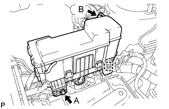
Engage the claw and install the engine room relay block.
-
Install the 2 bolts.
- Torque:
- Bolt A
- 5.4 N*m { 55 kgf*cm, 48 in.*lbf }
- Bolt B
- 8.4 N*m { 85 kgf*cm, 74 in.*lbf }
-
-
INSTALL BATTERY (for LHD)
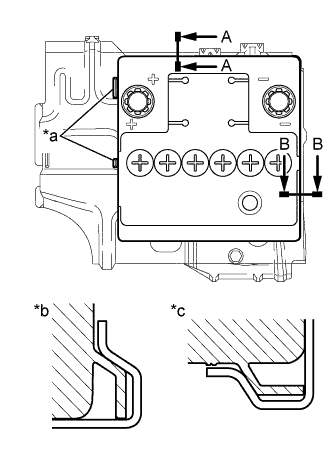
Text in Illustration *a Identification line *b A-A *c B-B
-
Install the battery onto the battery clamp sub-assembly, as shown in the illustration.
Note
-
The identification line should be seen after installing the battery.
-
The battery clamp should be in contact with the battery after the installation.
-
-
Install the battery clamp with the bolt.
- Torque:
- 15 N*m { 154 kgf*cm, 11 ft.*lbf }
-
Connect the battery positive (+) terminal with the nut.
- Torque:
- 5.4 N*m { 55 kgf*cm, 48 in.*lbf }
-
-
FILL RESERVOIR WITH BRAKE FLUID
Fluid SAE J1704 or FMVSS No. 116 DOT4 -
BLEED BRAKE MASTER CYLINDER
Tech Tips
If the master cylinder has been disassembled or if the reservoir becomes empty, bleed the air from the master cylinder.
-
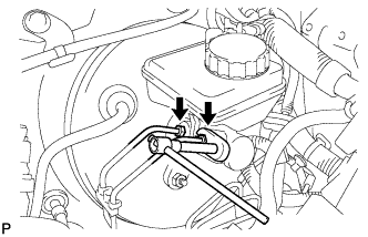
Using a 10 mm union nut wrench, separate the brake tubes from the master cylinder (w/o VSC).
-
Using a 12 mm union nut wrench, separate the brake tubes from the master cylinder (w/ VSC).
-
Slowly depress the brake pedal and hold it there (Step A).
-
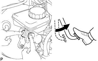
Block the outer holes with your fingers, and release the brake pedal (Step B).
-
Repeat step A and B 3 or 4 times.
-
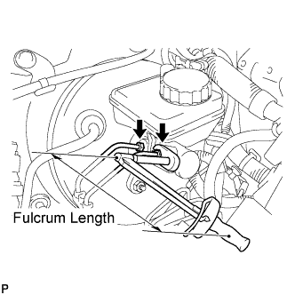
Using a 10 mm union nut wrench, install the brake tubes to the master cylinder (w/o VSC).
- Torque:
- without 10 mm union nut wrench
- 15 N*m { 155 kgf*cm, 11 ft.*lbf }
- with 10 mm union nut wrench
- 14 N*m { 143 kgf*cm, 10 ft.*lbf }
Note
-
This torque value can be obtained by using a torque wrench with a fulcrum length of 300 mm (11.8 in.) and a 10 mm union nut wrench with a fulcrum length of 22 mm (0.886 in.) Click here.
-
This torque value is effective when the union nut wrench is parallel to a torque wrench.
-
Using a 12 mm union nut wrench, install the brake tubes to the master cylinder (w/ VSC).
- Torque:
- without 12 mm union nut wrench
- 20 N*m { 204 kgf*cm, 15 ft.*lbf }
- with 12 mm union nut wrench
- 18 N*m { 184 kgf*cm, 13 ft.*lbf }
Note
-
This torque value can be obtained by using a torque wrench with a fulcrum length of 300 mm (11.8 in.) and a 12 mm union nut wrench with a fulcrum length of 30 mm (1.18 in.) Click here.
-
This torque value is effective when the union nut wrench is parallel to a torque wrench.
-
-
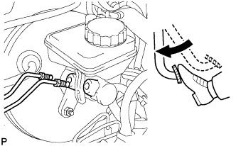
BLEED BRAKE LINE
-
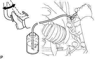
Connect a vinyl tube to the bleeder plug.
-
Depress the brake pedal several times, then loosen the bleeder plug with the pedal depressed (Step C).
-
At the point where the fluid stops coming out, tighten the bleeder plug, then release the brake pedal (Step D).
-
Repeat step C and D until all the air in the fluid is completely bled out.
-
Tighten the bleeder plug.
- Torque:
- 6.5 N*m { 66 kgf*cm, 58 in.*lbf }
-
Repeat the above procedure to bleed the air out of the brake line for each wheel.
-
-
CHECK FLUID LEVEL IN RESERVOIR
-
Check the fluid level and add fluid if necessary.
Fluid SAE J1704 or FMVSS No. 116 DOT4
-
-
INSTALL COWL TOP PANEL OUTER
-
Install the cowl top panel outer with the 10 bolts.
- Torque:
- 9.2 N*m { 94 kgf*cm, 81 in.*lbf }
-
Engage the grommet and install the wire harness.
-
Engage the wire harness clamp.
-
-
INSTALL FRONT NO. 1 VENTILATOR SEAL
-
Install the No. 1 ventilator seal with the 2 clips.
-
-
INSTALL FRONT AIR SHUTTER SEAL RH
-
Install the front air shutter seal RH the 2 clips.
-
-
INSTALL FRONT WIPER MOTOR AND LINK ASSEMBLY
-
INSTALL FRONT WHEEL (for RHD)
- Torque:
- 103 N*m { 1050 kgf*cm, 76 ft.*lbf }
-
CONNECT CABLE TO NEGATIVE BATTERY TERMINAL
- Torque:
- 5.4 N*m { 55 kgf*cm, 48 in.*lbf }
-
INSPECT FOR BRAKE FLUID LEAK