VEHICLE STABILITY CONTROL SYSTEM TC and CG Terminal Circuit
DESCRIPTION
Connecting terminals TC and CG of the DLC3 causes the skid control ECU to display 2-digit DTCs by flashing the ABS and VSC warning light.
WIRING DIAGRAM
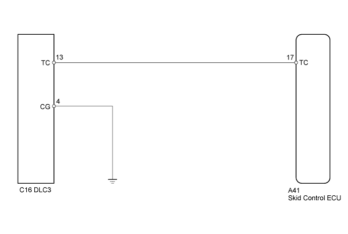
INSPECTION PROCEDURE
Tech Tips
When the warning lights continue to blink, a ground short in the wiring of terminal TC of the DLC3 or an internal ground short in one or more ECU is suspected.
PROCEDURE
-
CHECK DLC3 TERMINAL VOLTAGE (TC TERMINAL)
-
Turn the ignition switch to ON.
-
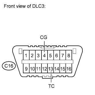
Measure the voltage according to the value(s) in the table below.
Standard voltage Tester Connection Switch Condition Specified Condition C16-13 (TC) - C16-4 (CG) Ignition switch ON 11 to 14 V
NG 
CHECK HARNESS AND CONNECTOR (DLC3 - BODY GROUND) Click here
OK 
-
-
CHECK HARNESS AND CONNECTOR (SKID CONTROL ECU - DLC3)
-
Disconnect the skid control ECU connector.
-
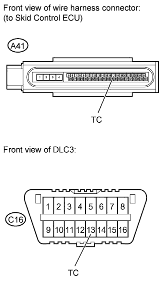
Measure the resistance according to the value(s) in the table below.
Standard resistance Tester Connection Condition Specified Condition A41-17 (TC) - C16-13 (TC) Always Below 1 Ω A41-17 (TC) - Body ground Always 10 kΩ or higher
NG 
REPAIR OR REPLACE HARNESS OR CONNECTOR
OK 
REPLACE BRAKE ACTUATOR ASSEMBLY Click here
-
-
CHECK HARNESS AND CONNECTOR (DLC3 - BODY GROUND)
-
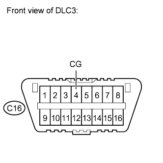
Measure the resistance according to the value(s) in the table below.
Standard resistance Tester Connection Condition Specified Condition C16-4 (CG) - Body ground Always Below 1 Ω
NG
REPAIR OR REPLACE HARNESS OR CONNECTOR
OK
-
-
CHECK HARNESS AND CONNECTOR (SKID CONTROL ECU - DLC3)
-
Disconnect the skid control ECU connector.
-
Measure the resistance according to the value(s) in the table below.
Standard resistance Tester Connection Condition Specified Condition A41-17 (TC) - C16-13 (TC) Always Below 1 Ω A41-17 (TC) - Body ground Always 10 kΩ or higher
NG
REPAIR OR REPLACE HARNESS OR CONNECTOR
OK
REPLACE BRAKE ACTUATOR ASSEMBLY Click here
-