VEHICLE STABILITY CONTROL SYSTEM Skid Control Buzzer Circuit
DESCRIPTION
The skid control buzzer sounds and the SLIP indicator blinks during VSC operation.
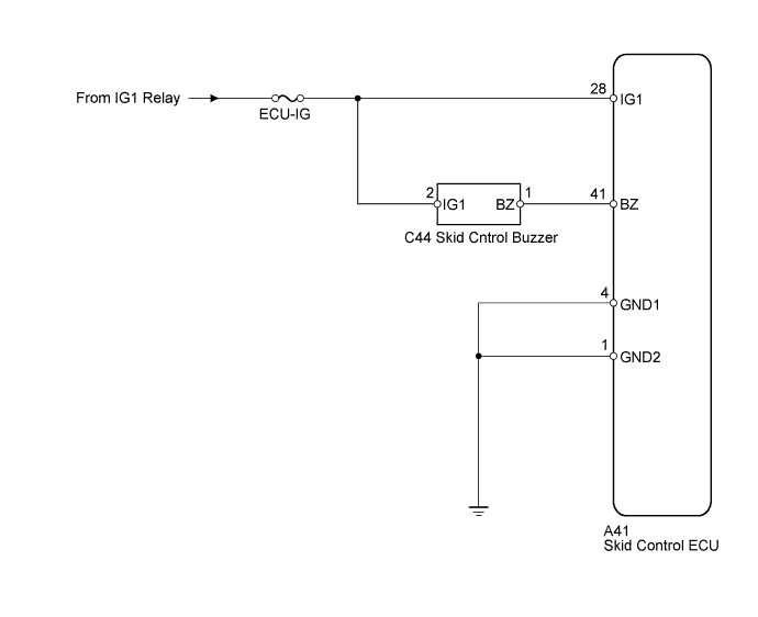
WIRING DIAGRAM
INSPECTION PROCEDURE
Tech Tips
Start the inspection from step 1 when using an intelligent tester and start from step 2 when not using an intelligent tester.
PROCEDURE
-
PERFORM ACTIVE TEST BY INTELLIGENT TESTER (SKID CONTROL BUZZER)
-
Connect the intelligent tester to the DLC3.
-
Start the engine.
-
Select the Active Test mode on the intelligent tester Click here.
ABS/TRC/VSC: Tester Display Test Part Control Range Diagnostic Note VSC H/B Warning Buzzer Skid control buzzer ON/OFF Buzzer ON/OFF Buzzer can be heard -
Check that the skid control buzzer sounds when operating it with the intelligent tester.
OK The skid control buzzer sounds in accordance with operation of the intelligent tester.
NG 
INSPECT SKID CONTROL BUZZER Click here
OK 
REPLACE BRAKE ACTUATOR ASSEMBLY Click here
-
-
INSPECT SKID CONTROL BUZZER
-
Disconnect the skid control buzzer connector.
-
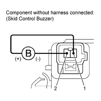
Apply a battery positive voltage to terminals 1 and 2 of the skid control buzzer connector, and check that the buzzer sounds.
OK The skid control buzzer sound should be heard.
NG 
REPLACE SKID CONTROL BUZZER
OK 
-
-
INSPECT SKID CONTROL BUZZER (POWER SOURCE)
-
Disconnect the skid control buzzer connector.
-
Turn the ignition switch to ON.
-
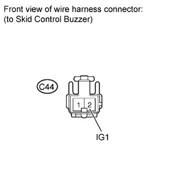
Measure the voltage according to the value(s) in the table below.
Standard voltage Tester Connection Switch Condition Specified Condition C44-2 (IG1) - Body ground Ignition switch ON 11 to 14 V
NG
REPAIR OR REPLACE SKID CONTROL BUZZER POWER SOURCE CIRCUIT
OK
-
-
CHECK HARNESS AND CONNECTOR (SKID CONTROL ECU - SKID CONTROL BUZZER)
-
Disconnect the skid control ECU connector and the skid control buzzer connector.
-
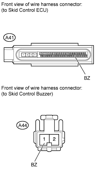
Measure the resistance according to the value(s) in the table below.
Standard resistance Tester Connection Switch Condition Specified Condition A41-41 (BZ) - C44-1 (BZ) Always Below 1 Ω A41-41 (BZ) - Body ground Always 10 kΩ or higher
NG
REPAIR OR REPLACE HARNESS OR CONNECTOR
OK
REPLACE BRAKE ACTUATOR ASSEMBLY Click here
-